HP 8100 Maintenance and Service Guide: HP Compaq 8100 and 8180 Elite Business - Page 60
Installing DIMMs, CAUTION, WARNING
 |
View all HP 8100 manuals
Add to My Manuals
Save this manual to your list of manuals |
Page 60 highlights
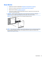
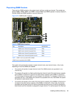
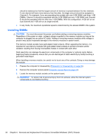
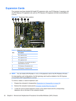
should be balanced so that the largest amount of memory is spread between the two channels. If one channel will have more memory than the other, the larger amount should be assigned to Channel A. For example, if you are populating the sockets with one 2-GB DIMM, and three 1-GB DIMMs, Channel A should be populated with the 2-GB DIMM and one 1-GB DIMM, and Channel B should be populated with the other two 1-GB DIMMs. With this configuration, 4-GB will run as dual channel and 1-GB will run as single channel. ● In any mode, the maximum operational speed is determined by the slowest DIMM in the system. Installing DIMMs CAUTION: You must disconnect the power cord before adding or removing memory modules. Regardless of the power-on state, voltage is always supplied to the memory modules as long as the computer is plugged into an active AC outlet. Adding or removing memory modules while voltage is present may cause irreparable damage to the memory modules or system board. The memory module sockets have gold-plated metal contacts. When upgrading the memory, it is important to use memory modules with gold-plated metal contacts to prevent corrosion and/or oxidation resulting from having incompatible metals in contact with each other. Static electricity can damage the electronic components of the computer or optional cards. Before beginning these procedures, ensure that you are discharged of static electricity by briefly touching a grounded metal object. When handling a memory module, be careful not to touch any of the contacts. Doing so may damage the module. 1. Prepare the computer for disassembly (Preparation for Disassembly on page 35). 2. Remove the computer access panel (Computer Access Panel on page 43). 3. Locate the memory module sockets on the system board. WARNING! To reduce risk of personal injury from hot surfaces, allow the internal system components to cool before touching. 50 Chapter 6 Removal and Replacement Procedures Convertible Minitower (CMT) Chassis
-
 1
1 -
2
-
3
-
4
-
5
-
6
-
7
-
8
-
9
-
10
-
11
-
12
-
13
-
14
-
15
-
16
-
17
-
18
-
19
-
20
-
21
-
22
-
23
-
24
-
25
-
26
-
27
-
28
-
29
-
30
-
31
-
32
-
33
-
34
-
35
-
36
-
37
-
38
-
39
-
40
-
41
-
42
-
43
-
44
-
45
-
46
-
47
-
48
-
49
-
50
-
51
-
52
-
53
-
54
-
 55
55 -
 56
56 -
 57
57 -
 58
58 -
 59
59 -
 60
60 -
 61
61 -
 62
62 -
 63
63 -
 64
64 -
 65
65 -
66
-
67
-
68
-
69
-
70
-
71
-
72
-
73
-
74
-
75
-
76
-
77
-
78
-
79
-
80
-
81
-
82
-
83
-
84
-
85
-
86
-
87
-
88
-
89
-
90
-
91
-
92
-
93
-
94
-
95
-
96
-
97
-
98
-
99
-
100
-
101
-
102
-
103
-
104
-
105
-
106
-
107
-
108
-
109
-
110
-
111
-
112
-
113
-
114
-
115
-
116
-
117
-
118
-
119
-
120
-
121
-
122
-
123
-
124
-
125
-
126
-
127
-
128
-
129
-
130
-
131
-
132
-
133
-
134
-
135
-
136
-
137
-
138
-
139
-
140
-
141
-
142
-
143
-
144
-
145
-
146
-
147
-
148
-
149
-
150
-
151
-
152
-
153
-
154
-
155
-
156
-
157
-
158
-
159
-
160
-
161
-
162
-
163
-
164
-
165
-
166
-
167
-
168
-
169
-
170
-
171
-
172
-
173
-
174
-
175
-
176
-
177
-
178
-
179
-
180
-
181
-
182
-
183
-
184
-
185
-
186
-
187
-
188
-
189
-
190
-
191
-
192
-
193
-
194
-
195
-
196
-
197
-
198
-
199
-
200
-
201
-
202
-
203
-
204
-
205
-
206
-
207
-
208
-
209
-
210
-
211
-
212
-
213
-
214
-
215
-
216
-
217
-
218
-
219
-
220
-
221
-
222
-
223
-
224
-
225
-
226
-
227
-
228
-
229
-
230
-
231
-
232
-
233
-
234
-
235
-
236
-
237
-
238
-
239
-
240
-
241
-
242
-
243
-
244
-
245
-
246
-
247
-
248
 |
 |