HP 8100 Maintenance and Service Guide: HP Compaq 8100 and 8180 Elite Business - Page 75
Installing a 3.5-inch SATA Hard Drive into an Internal Drive Bay, CAUTION
 |
View all HP 8100 manuals
Add to My Manuals
Save this manual to your list of manuals |
Page 75 highlights
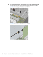
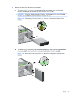
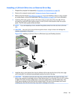
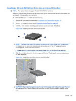
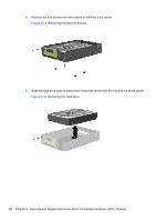
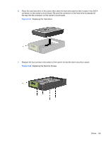
Installing a 3.5-inch SATA Hard Drive into an Internal Drive Bay NOTE: The system does not support Parallel ATA (PATA) hard drives. Before you remove the old hard drive, be sure to back up the data from the old hard drive so that you can transfer the data to the new hard drive. To install a hard drive in a 3.5-inch internal drive bay: 1. Prepare the computer for disassembly (Preparation for Disassembly on page 35). 2. Remove the computer access panel (Computer Access Panel on page 43). 3. Install four 6-32 isolation mounting guide screws, two on each side of the drive. Figure 6-34 Installing the Hard Drive Guide Screws NOTE: The hard drive uses 6-32 isolation mounting guide screws. Eight extra guide screws are installed on the hard drive bracket under the access panel. The HP-supplied isolation mounting guide screws are silver and blue. If you are replacing a drive, transfer the guides screws from the old drive to the new one. 4. Slide the hard drive down into the drive cage until it locks. The drivelock automatically secures the drive in the bay. Figure 6-35 Installing a Hard Drive into the Hard Drive Bay CAUTION: Make sure the guide screws line up with the guide slots in the drive cage. The use of unnecessary force when installing any drive into the drive bay may result in damage to the drive. Drives 65
-
 1
1 -
2
-
3
-
4
-
5
-
6
-
7
-
8
-
9
-
10
-
11
-
12
-
13
-
14
-
15
-
16
-
17
-
18
-
19
-
20
-
21
-
22
-
23
-
24
-
25
-
26
-
27
-
28
-
29
-
30
-
31
-
32
-
33
-
34
-
35
-
36
-
37
-
38
-
39
-
40
-
41
-
42
-
43
-
44
-
45
-
46
-
47
-
48
-
49
-
50
-
51
-
52
-
53
-
54
-
55
-
56
-
57
-
58
-
59
-
60
-
61
-
62
-
63
-
64
-
65
-
66
-
67
-
68
-
69
-
 70
70 -
 71
71 -
 72
72 -
 73
73 -
 74
74 -
 75
75 -
 76
76 -
 77
77 -
 78
78 -
 79
79 -
 80
80 -
81
-
82
-
83
-
84
-
85
-
86
-
87
-
88
-
89
-
90
-
91
-
92
-
93
-
94
-
95
-
96
-
97
-
98
-
99
-
100
-
101
-
102
-
103
-
104
-
105
-
106
-
107
-
108
-
109
-
110
-
111
-
112
-
113
-
114
-
115
-
116
-
117
-
118
-
119
-
120
-
121
-
122
-
123
-
124
-
125
-
126
-
127
-
128
-
129
-
130
-
131
-
132
-
133
-
134
-
135
-
136
-
137
-
138
-
139
-
140
-
141
-
142
-
143
-
144
-
145
-
146
-
147
-
148
-
149
-
150
-
151
-
152
-
153
-
154
-
155
-
156
-
157
-
158
-
159
-
160
-
161
-
162
-
163
-
164
-
165
-
166
-
167
-
168
-
169
-
170
-
171
-
172
-
173
-
174
-
175
-
176
-
177
-
178
-
179
-
180
-
181
-
182
-
183
-
184
-
185
-
186
-
187
-
188
-
189
-
190
-
191
-
192
-
193
-
194
-
195
-
196
-
197
-
198
-
199
-
200
-
201
-
202
-
203
-
204
-
205
-
206
-
207
-
208
-
209
-
210
-
211
-
212
-
213
-
214
-
215
-
216
-
217
-
218
-
219
-
220
-
221
-
222
-
223
-
224
-
225
-
226
-
227
-
228
-
229
-
230
-
231
-
232
-
233
-
234
-
235
-
236
-
237
-
238
-
239
-
240
-
241
-
242
-
243
-
244
-
245
-
246
-
247
-
248
 |
 |