HP 8100 Maintenance and Service Guide: HP Compaq 8100 and 8180 Elite Business - Page 83
Front I/O, USB Assembly, Blue connector labeled FRONT AUD
 |
View all HP 8100 manuals
Add to My Manuals
Save this manual to your list of manuals |
Page 83 highlights
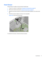
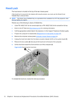
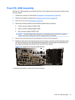
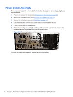
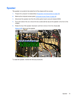
Front I/O, USB Assembly The front I/O, USB assembly is mounted to the front of the chassis and is removed by pulling it away from the chassis. 1. Prepare the computer for disassembly (Preparation for Disassembly on page 35). 2. Remove the computer access panel (Computer Access Panel on page 43). 3. Remove the front bezel (Front Bezel on page 44). 4. Disconnect the three cables from the following system board connectors: ● Yellow connector labeled FRONT USB ● Green connector labeled FRONT USB2 ● Blue connector labeled FRONT AUD NOTE: The blue FRONT AUD connector is not located near the other two connectors used for the front I/O assembly. See the image below for its location. 5. Remove the screw that secures the assembly to the front of the chassis (1). 6. Rotate the right side of the assembly away from the chassis, and then pull the assembly toward the right and away from the chassis (2) while threading the wires through the slot between the drive cage and chassis front and the hole in the front of the chassis. Figure 6-47 Removing the front I/O, USB assembly To reinstall the assembly, reverse the removal procedure. Front I/O, USB Assembly 73
-
 1
1 -
2
-
3
-
4
-
5
-
6
-
7
-
8
-
9
-
10
-
11
-
12
-
13
-
14
-
15
-
16
-
17
-
18
-
19
-
20
-
21
-
22
-
23
-
24
-
25
-
26
-
27
-
28
-
29
-
30
-
31
-
32
-
33
-
34
-
35
-
36
-
37
-
38
-
39
-
40
-
41
-
42
-
43
-
44
-
45
-
46
-
47
-
48
-
49
-
50
-
51
-
52
-
53
-
54
-
55
-
56
-
57
-
58
-
59
-
60
-
61
-
62
-
63
-
64
-
65
-
66
-
67
-
68
-
69
-
70
-
71
-
72
-
73
-
74
-
75
-
76
-
77
-
 78
78 -
 79
79 -
 80
80 -
 81
81 -
 82
82 -
 83
83 -
 84
84 -
 85
85 -
 86
86 -
 87
87 -
 88
88 -
89
-
90
-
91
-
92
-
93
-
94
-
95
-
96
-
97
-
98
-
99
-
100
-
101
-
102
-
103
-
104
-
105
-
106
-
107
-
108
-
109
-
110
-
111
-
112
-
113
-
114
-
115
-
116
-
117
-
118
-
119
-
120
-
121
-
122
-
123
-
124
-
125
-
126
-
127
-
128
-
129
-
130
-
131
-
132
-
133
-
134
-
135
-
136
-
137
-
138
-
139
-
140
-
141
-
142
-
143
-
144
-
145
-
146
-
147
-
148
-
149
-
150
-
151
-
152
-
153
-
154
-
155
-
156
-
157
-
158
-
159
-
160
-
161
-
162
-
163
-
164
-
165
-
166
-
167
-
168
-
169
-
170
-
171
-
172
-
173
-
174
-
175
-
176
-
177
-
178
-
179
-
180
-
181
-
182
-
183
-
184
-
185
-
186
-
187
-
188
-
189
-
190
-
191
-
192
-
193
-
194
-
195
-
196
-
197
-
198
-
199
-
200
-
201
-
202
-
203
-
204
-
205
-
206
-
207
-
208
-
209
-
210
-
211
-
212
-
213
-
214
-
215
-
216
-
217
-
218
-
219
-
220
-
221
-
222
-
223
-
224
-
225
-
226
-
227
-
228
-
229
-
230
-
231
-
232
-
233
-
234
-
235
-
236
-
237
-
238
-
239
-
240
-
241
-
242
-
243
-
244
-
245
-
246
-
247
-
248
 |
 |
