HP 8100 Maintenance and Service Guide: HP Compaq 8100 and 8180 Elite Business - Page 73
Installing a 5.25-inch Drive into an External Drive Bay, CAUTION,
 |
View all HP 8100 manuals
Add to My Manuals
Save this manual to your list of manuals |
Page 73 highlights
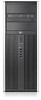
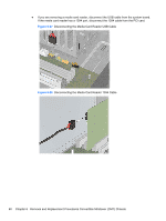
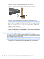
Installing a 5.25-inch Drive into an External Drive Bay 1. Prepare the computer for disassembly (Preparation for Disassembly on page 35). 2. Remove the computer access panel (Computer Access Panel on page 43). 3. Remove the front bezel (Front Bezel on page 44). If you are installing a drive in a bay covered by a bezel blank, remove the bezel blank. See Bezel Blanks on page 45 for more information. 4. Install four M3 metric guide screws in the lower holes on each side of the drive (1). HP has provided four extra M3 metric guide screws on the 5.25-inch drive bracket under the access panel. The M3 metric guide screws are black. NOTE: If you are replacing a drive, transfer the guides screws from the old drive to the new one. CAUTION: Use only 5-mm long screws as guide screws. Longer screws can damage the internal components of the drive. Figure 6-32 Installing a 5.25-Inch Drive in a Minitower (top) and Desktop (bottom) 5. Install the drive in the desired drive bay by sliding it all the way into the front of the drive cage until it locks (2). The drivelock automatically secures the drive in the bay. CAUTION: The bottom 5.25-inch drive bay has a shorter depth than the upper two bays. The bottom bay supports a half-height drive or other device that is no more than 14.5 cm (5.7 inches) in depth. Do not try to force a larger drive, such as an optical drive, into the bottom bay. This could cause damage to the drive and the system board. The use of unnecessary force when installing any drive into the drive bay may result in damage to the drive. Drives 63
-
 1
1 -
2
-
3
-
4
-
5
-
6
-
7
-
8
-
9
-
10
-
11
-
12
-
13
-
14
-
15
-
16
-
17
-
18
-
19
-
20
-
21
-
22
-
23
-
24
-
25
-
26
-
27
-
28
-
29
-
30
-
31
-
32
-
33
-
34
-
35
-
36
-
37
-
38
-
39
-
40
-
41
-
42
-
43
-
44
-
45
-
46
-
47
-
48
-
49
-
50
-
51
-
52
-
53
-
54
-
55
-
56
-
57
-
58
-
59
-
60
-
61
-
62
-
63
-
64
-
65
-
66
-
67
-
 68
68 -
 69
69 -
 70
70 -
 71
71 -
 72
72 -
 73
73 -
 74
74 -
 75
75 -
 76
76 -
 77
77 -
 78
78 -
79
-
80
-
81
-
82
-
83
-
84
-
85
-
86
-
87
-
88
-
89
-
90
-
91
-
92
-
93
-
94
-
95
-
96
-
97
-
98
-
99
-
100
-
101
-
102
-
103
-
104
-
105
-
106
-
107
-
108
-
109
-
110
-
111
-
112
-
113
-
114
-
115
-
116
-
117
-
118
-
119
-
120
-
121
-
122
-
123
-
124
-
125
-
126
-
127
-
128
-
129
-
130
-
131
-
132
-
133
-
134
-
135
-
136
-
137
-
138
-
139
-
140
-
141
-
142
-
143
-
144
-
145
-
146
-
147
-
148
-
149
-
150
-
151
-
152
-
153
-
154
-
155
-
156
-
157
-
158
-
159
-
160
-
161
-
162
-
163
-
164
-
165
-
166
-
167
-
168
-
169
-
170
-
171
-
172
-
173
-
174
-
175
-
176
-
177
-
178
-
179
-
180
-
181
-
182
-
183
-
184
-
185
-
186
-
187
-
188
-
189
-
190
-
191
-
192
-
193
-
194
-
195
-
196
-
197
-
198
-
199
-
200
-
201
-
202
-
203
-
204
-
205
-
206
-
207
-
208
-
209
-
210
-
211
-
212
-
213
-
214
-
215
-
216
-
217
-
218
-
219
-
220
-
221
-
222
-
223
-
224
-
225
-
226
-
227
-
228
-
229
-
230
-
231
-
232
-
233
-
234
-
235
-
236
-
237
-
238
-
239
-
240
-
241
-
242
-
243
-
244
-
245
-
246
-
247
-
248
 |
 |