HP 8100 Maintenance and Service Guide: HP Compaq 8100 and 8180 Elite Business - Page 123
Installing and Removing Drives,
 |
View all HP 8100 manuals
Add to My Manuals
Save this manual to your list of manuals |
Page 123 highlights
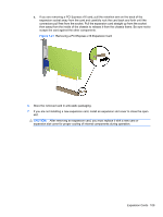
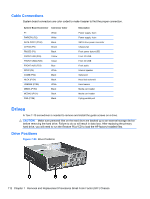
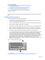
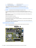
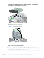
Table 7-3 Drive Positions 1 3.5-inch internal hard drive bay 2 3.5-inch external drive bay for optional drives (media card reader shown) 3 5.25-inch external drive bay for optional drives (optical drive shown) NOTE: The drive configuration on your computer may be different than the drive configuration shown above. To verify the type, size, and capacity of the storage devices installed in the computer, run Computer Setup. Installing and Removing Drives When installing additional drives, follow these guidelines: ● The primary Serial ATA (SATA) hard drive must be connected to the dark blue primary SATA connector on the system board labeled SATA0. ● Connect a SATA optical drive to the white SATA connector on the system board labeled SATA1. ● Connect devices in order of SATA0, SATA1, then SATA2 ● Connect an optional eSATA adapter cable to the black ESATA connector on the system board. ● Connect a media card reader USB cable to the USB connector on the system board labeled MEDIA. If the media card reader has a 1394 port, connect the 1394 cable to the 1394 PCI card. ● The system does not support Parallel ATA (PATA) optical drives or PATA hard drives. ● You must install guide screws to ensure the drive will line up correctly in the drive cage and lock in place. HP has provided extra guide screws for the external drive bays (five 6-32 standard screws and four M3 metric screws), installed in the front of the chassis, under the front bezel. The 6-32 standard screws are required for a secondary hard drive. All other drives (except the primary hard drive) use M3 metric screws. The HP-supplied metric screws are black and the HPsupplied standard screws are silver. If you are replacing the primary hard drive, you must remove the four silver and blue 6-32 isolation mounting guide screws from the old hard drive and install them in the new hard drive. Figure 7-25 Extra Guide Screw Locations No. Guide Screw Device Drives 113
-
 1
1 -
2
-
3
-
4
-
5
-
6
-
7
-
8
-
9
-
10
-
11
-
12
-
13
-
14
-
15
-
16
-
17
-
18
-
19
-
20
-
21
-
22
-
23
-
24
-
25
-
26
-
27
-
28
-
29
-
30
-
31
-
32
-
33
-
34
-
35
-
36
-
37
-
38
-
39
-
40
-
41
-
42
-
43
-
44
-
45
-
46
-
47
-
48
-
49
-
50
-
51
-
52
-
53
-
54
-
55
-
56
-
57
-
58
-
59
-
60
-
61
-
62
-
63
-
64
-
65
-
66
-
67
-
68
-
69
-
70
-
71
-
72
-
73
-
74
-
75
-
76
-
77
-
78
-
79
-
80
-
81
-
82
-
83
-
84
-
85
-
86
-
87
-
88
-
89
-
90
-
91
-
92
-
93
-
94
-
95
-
96
-
97
-
98
-
99
-
100
-
101
-
102
-
103
-
104
-
105
-
106
-
107
-
108
-
109
-
110
-
111
-
112
-
113
-
114
-
115
-
116
-
117
-
 118
118 -
 119
119 -
 120
120 -
 121
121 -
 122
122 -
 123
123 -
 124
124 -
 125
125 -
 126
126 -
 127
127 -
 128
128 -
129
-
130
-
131
-
132
-
133
-
134
-
135
-
136
-
137
-
138
-
139
-
140
-
141
-
142
-
143
-
144
-
145
-
146
-
147
-
148
-
149
-
150
-
151
-
152
-
153
-
154
-
155
-
156
-
157
-
158
-
159
-
160
-
161
-
162
-
163
-
164
-
165
-
166
-
167
-
168
-
169
-
170
-
171
-
172
-
173
-
174
-
175
-
176
-
177
-
178
-
179
-
180
-
181
-
182
-
183
-
184
-
185
-
186
-
187
-
188
-
189
-
190
-
191
-
192
-
193
-
194
-
195
-
196
-
197
-
198
-
199
-
200
-
201
-
202
-
203
-
204
-
205
-
206
-
207
-
208
-
209
-
210
-
211
-
212
-
213
-
214
-
215
-
216
-
217
-
218
-
219
-
220
-
221
-
222
-
223
-
224
-
225
-
226
-
227
-
228
-
229
-
230
-
231
-
232
-
233
-
234
-
235
-
236
-
237
-
238
-
239
-
240
-
241
-
242
-
243
-
244
-
245
-
246
-
247
-
248
 |
 |