HP 8100 Maintenance and Service Guide: HP Compaq 8100 and 8180 Elite Business - Page 147
CAUTION, Preparation for Disassembly, on Computer Access Panel, Baffle
 |
View all HP 8100 manuals
Add to My Manuals
Save this manual to your list of manuals |
Page 147 highlights
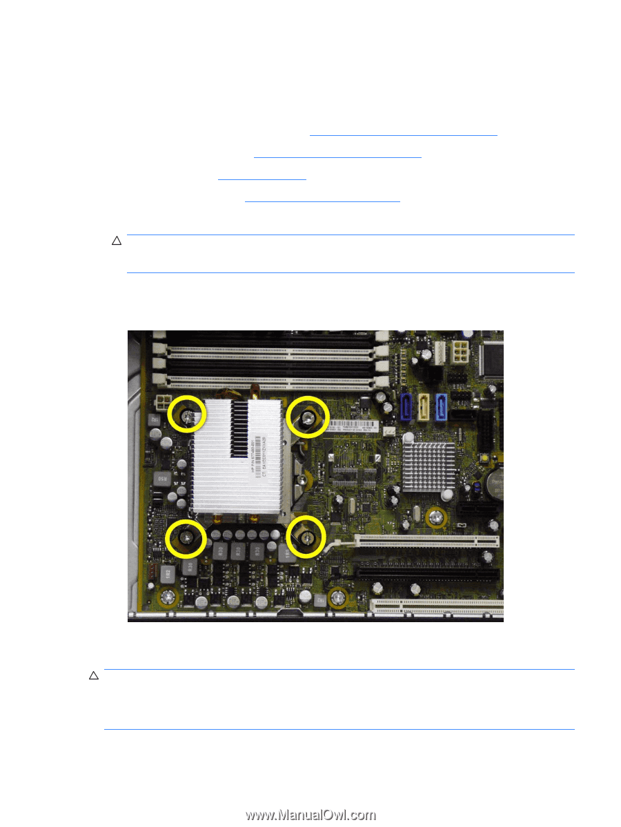
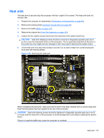
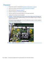
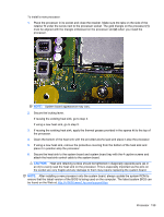
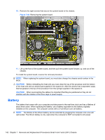
Heat sink The heat sink is secured atop the processor with four captive Torx screws. The heat sink does not include a fan. 1. Prepare the computer for disassembly (Preparation for Disassembly on page 90). 2. Remove the access panel (Computer Access Panel on page 99). 3. Remove the baffle (Baffle on page 131). 4. Remove the chassis fan (Front Fan Assembly on page 132). 5. Loosen the four captive screws that secure the heat sink to the system board tray. CAUTION: Heat sink retaining screws should be removed in diagonally opposite pairs (as in an X) to even the downward forces on the processor. This is especially important as the pins on the socket are very fragile and any damage to them may require replacing the system board. 6. Lift the heat sink from atop the processor and set it on its side to keep from contaminating the work area with thermal grease. Figure 7-59 Removing the heat sink When reinstalling the heat sink, make sure that its bottom has been cleaned with an alcohol wipe and fresh thermal grease has been applied to the top of the processor. CAUTION: Heat sink retaining screws should be tightened in diagonally opposite pairs (as in an X) to evenly seat the heat sink on the processor to avoid damage that could require replacing the system board. Failure to install the baffle may cause the computer to overheat. Heat sink 137
-
 1
1 -
2
-
3
-
4
-
5
-
6
-
7
-
8
-
9
-
10
-
11
-
12
-
13
-
14
-
15
-
16
-
17
-
18
-
19
-
20
-
21
-
22
-
23
-
24
-
25
-
26
-
27
-
28
-
29
-
30
-
31
-
32
-
33
-
34
-
35
-
36
-
37
-
38
-
39
-
40
-
41
-
42
-
43
-
44
-
45
-
46
-
47
-
48
-
49
-
50
-
51
-
52
-
53
-
54
-
55
-
56
-
57
-
58
-
59
-
60
-
61
-
62
-
63
-
64
-
65
-
66
-
67
-
68
-
69
-
70
-
71
-
72
-
73
-
74
-
75
-
76
-
77
-
78
-
79
-
80
-
81
-
82
-
83
-
84
-
85
-
86
-
87
-
88
-
89
-
90
-
91
-
92
-
93
-
94
-
95
-
96
-
97
-
98
-
99
-
100
-
101
-
102
-
103
-
104
-
105
-
106
-
107
-
108
-
109
-
110
-
111
-
112
-
113
-
114
-
115
-
116
-
117
-
118
-
119
-
120
-
121
-
122
-
123
-
124
-
125
-
126
-
127
-
128
-
129
-
130
-
131
-
132
-
133
-
134
-
135
-
136
-
137
-
138
-
139
-
140
-
141
-
 142
142 -
 143
143 -
 144
144 -
 145
145 -
 146
146 -
 147
147 -
 148
148 -
 149
149 -
 150
150 -
 151
151 -
 152
152 -
153
-
154
-
155
-
156
-
157
-
158
-
159
-
160
-
161
-
162
-
163
-
164
-
165
-
166
-
167
-
168
-
169
-
170
-
171
-
172
-
173
-
174
-
175
-
176
-
177
-
178
-
179
-
180
-
181
-
182
-
183
-
184
-
185
-
186
-
187
-
188
-
189
-
190
-
191
-
192
-
193
-
194
-
195
-
196
-
197
-
198
-
199
-
200
-
201
-
202
-
203
-
204
-
205
-
206
-
207
-
208
-
209
-
210
-
211
-
212
-
213
-
214
-
215
-
216
-
217
-
218
-
219
-
220
-
221
-
222
-
223
-
224
-
225
-
226
-
227
-
228
-
229
-
230
-
231
-
232
-
233
-
234
-
235
-
236
-
237
-
238
-
239
-
240
-
241
-
242
-
243
-
244
-
245
-
246
-
247
-
248
 |
 |