HP 8100 Maintenance and Service Guide: HP Compaq 8100 and 8180 Elite Business - Page 74
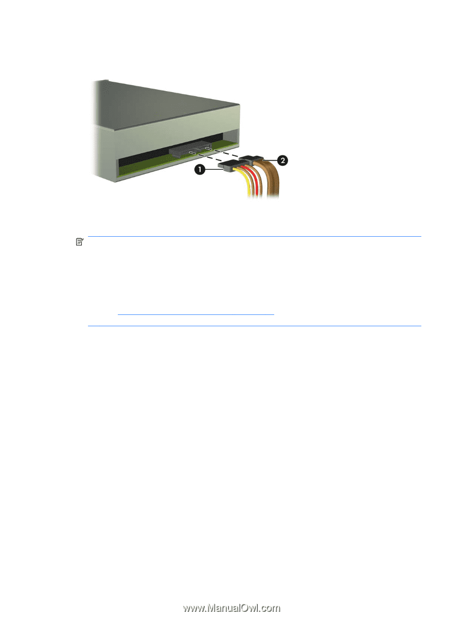
Connecting the Drive Cables Optical Drive shown,
 |
View all HP 8100 manuals
Add to My Manuals
Save this manual to your list of manuals |
Page 74 highlights
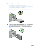
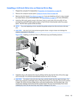
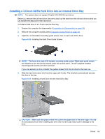
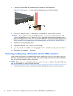
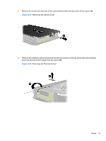
6. Connect the power cable (1) and data cable (2) to the rear of the drive. Figure 6-33 Connecting the Drive Cables (Optical Drive shown) 7. If you are installing a new drive, connect the opposite end of the data cable to the appropriate system board connector. NOTE: If you are installing a SATA optical drive, connect the first optical drive to the white SATA connector on the system board labeled SATA1. Connect a second optical drive to the next available (unpopulated) SATA connector following the numbered sequence of the connectors. If your are installing a media card reader, connect the USB cable to the USB system board connector labeled MEDIA. If the media card reader includes a 1394 port, connect the 1394 cable to the 1394 PCI card. Refer to System Board Drive Connections on page 57 for an illustration of the system board drive connectors. 8. Replace the front bezel and computer access panel. 9. Reconnect the power cord and turn on the computer. 10. Lock any security devices that were disengaged when the computer access panel was removed. 11. Reconfigure the computer, if necessary. 64 Chapter 6 Removal and Replacement Procedures Convertible Minitower (CMT) Chassis
-
 1
1 -
2
-
3
-
4
-
5
-
6
-
7
-
8
-
9
-
10
-
11
-
12
-
13
-
14
-
15
-
16
-
17
-
18
-
19
-
20
-
21
-
22
-
23
-
24
-
25
-
26
-
27
-
28
-
29
-
30
-
31
-
32
-
33
-
34
-
35
-
36
-
37
-
38
-
39
-
40
-
41
-
42
-
43
-
44
-
45
-
46
-
47
-
48
-
49
-
50
-
51
-
52
-
53
-
54
-
55
-
56
-
57
-
58
-
59
-
60
-
61
-
62
-
63
-
64
-
65
-
66
-
67
-
68
-
 69
69 -
 70
70 -
 71
71 -
 72
72 -
 73
73 -
 74
74 -
 75
75 -
 76
76 -
 77
77 -
 78
78 -
 79
79 -
80
-
81
-
82
-
83
-
84
-
85
-
86
-
87
-
88
-
89
-
90
-
91
-
92
-
93
-
94
-
95
-
96
-
97
-
98
-
99
-
100
-
101
-
102
-
103
-
104
-
105
-
106
-
107
-
108
-
109
-
110
-
111
-
112
-
113
-
114
-
115
-
116
-
117
-
118
-
119
-
120
-
121
-
122
-
123
-
124
-
125
-
126
-
127
-
128
-
129
-
130
-
131
-
132
-
133
-
134
-
135
-
136
-
137
-
138
-
139
-
140
-
141
-
142
-
143
-
144
-
145
-
146
-
147
-
148
-
149
-
150
-
151
-
152
-
153
-
154
-
155
-
156
-
157
-
158
-
159
-
160
-
161
-
162
-
163
-
164
-
165
-
166
-
167
-
168
-
169
-
170
-
171
-
172
-
173
-
174
-
175
-
176
-
177
-
178
-
179
-
180
-
181
-
182
-
183
-
184
-
185
-
186
-
187
-
188
-
189
-
190
-
191
-
192
-
193
-
194
-
195
-
196
-
197
-
198
-
199
-
200
-
201
-
202
-
203
-
204
-
205
-
206
-
207
-
208
-
209
-
210
-
211
-
212
-
213
-
214
-
215
-
216
-
217
-
218
-
219
-
220
-
221
-
222
-
223
-
224
-
225
-
226
-
227
-
228
-
229
-
230
-
231
-
232
-
233
-
234
-
235
-
236
-
237
-
238
-
239
-
240
-
241
-
242
-
243
-
244
-
245
-
246
-
247
-
248
 |
 |