HP Disk System 2300 HP StorageWorks Disk System 2300 User's Guide(This manual - Page 15
Status Indicators, see Troubleshooting.
 |
View all HP Disk System 2300 manuals
Add to My Manuals
Save this manual to your list of manuals |
Page 15 highlights
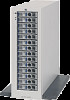
Product Description Status Indicators LEDs on the disk system enable you to detect and replace failed components and so prevent or minimize users' downtime. For additional information about LEDs, see Chapter 4, Troubleshooting. On the front of the disk system, a pair of LEDs indicates the status of the disk system, and an LED for each slot shows disk I/O activity: ■ The system power LED (B in Figure 1) indicates that power is on or off. ■ The system fault LED (C in Figure 1) indicates whether or not a fault has occurred anywhere in the disk system. ■ At the bottom of each disk module, the left LED (F in Figure 1) indicates the presence of I/O activity on the disk. ■ The second LED on each disk module (E in Figure 1) can be flashed to help a customer engineer (CE) locate the disk for physical inspection or removal. ■ The second LED is also used as a fault indicator for that specific disk module. LEDs (I and K in Figure 2) on the back of the disk system indicate the status of replaceable components and the SCSI bus: See Chapter 4, Troubleshooting, for specific LED information. Product Description 15
-
 1
1 -
2
-
3
-
4
-
5
-
6
-
7
-
8
-
9
-
 10
10 -
 11
11 -
 12
12 -
 13
13 -
 14
14 -
 15
15 -
 16
16 -
 17
17 -
 18
18 -
 19
19 -
 20
20 -
21
-
22
-
23
-
24
-
25
-
26
-
27
-
28
-
29
-
30
-
31
-
32
-
33
-
34
-
35
-
36
-
37
-
38
-
39
-
40
-
41
-
42
-
43
-
44
-
45
-
46
-
47
-
48
-
49
-
50
-
51
-
52
-
53
-
54
-
55
-
56
-
57
-
58
-
59
-
60
-
61
-
62
-
63
-
64
-
65
-
66
-
67
-
68
-
69
-
70
-
71
-
72
-
73
-
74
-
75
-
76
-
77
-
78
-
79
-
80
-
81
-
82
-
83
-
84
-
85
-
86
-
87
-
88
-
89
-
90
-
91
-
92
-
93
-
94
-
95
-
96
-
97
-
98
-
99
-
100
-
101
-
102
-
103
-
104
-
105
-
106
-
107
-
108
-
109
-
110
-
111
-
112
-
113
-
114
-
115
-
116
-
117
-
118
-
119
-
120
-
121
-
122
-
123
-
124
-
125
-
126
-
127
-
128
-
129
-
130
-
131
-
132
-
133
-
134
-
135
-
136
-
137
-
138
-
139
-
140
-
141
-
142
-
143
-
144
-
145
-
146
-
147
-
148
-
149
-
150
-
151
-
152
-
153
-
154
-
155
-
156
-
157
-
158
 |
 |
