HP Disk System 2300 HP StorageWorks Disk System 2300 User's Guide(This manual - Page 74
Step 5: Set DIP Switches, There is a switch bank that is recessed from the BCC bulkhead. Typically
 |
View all HP Disk System 2300 manuals
Add to My Manuals
Save this manual to your list of manuals |
Page 74 highlights
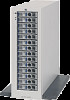
Step 5: Set DIP Switches BCCs are shipped from the factory with all DIP switches (see Figure 43) in the "|" position. The pull-out label on top of the disk system identifies each switch position. Caution DIP Switch settings must be the same on both BCCs. If settings differ, the disk system will fail its power-on self-test and the disks will not be accessible through the second BCC. Set dip switches as needed. See Chapter 3, Configuration, for switch definitions and guidelines. There is a switch bank that is recessed from the BCC bulkhead. Typically, they do not need to be reset. The BCC must be removed from the disk system to access this switch bank. See switch bank 2 in Chapter 3. Also see Tables 33 and 34 for switch settings and usage. 74 Installation
-
 1
1 -
2
-
3
-
4
-
5
-
6
-
7
-
8
-
9
-
10
-
11
-
12
-
13
-
14
-
15
-
16
-
17
-
18
-
19
-
20
-
21
-
22
-
23
-
24
-
25
-
26
-
27
-
28
-
29
-
30
-
31
-
32
-
33
-
34
-
35
-
36
-
37
-
38
-
39
-
40
-
41
-
42
-
43
-
44
-
45
-
46
-
47
-
48
-
49
-
50
-
51
-
52
-
53
-
54
-
55
-
56
-
57
-
58
-
59
-
60
-
61
-
62
-
63
-
64
-
65
-
66
-
67
-
68
-
 69
69 -
 70
70 -
 71
71 -
 72
72 -
 73
73 -
 74
74 -
 75
75 -
 76
76 -
 77
77 -
 78
78 -
 79
79 -
80
-
81
-
82
-
83
-
84
-
85
-
86
-
87
-
88
-
89
-
90
-
91
-
92
-
93
-
94
-
95
-
96
-
97
-
98
-
99
-
100
-
101
-
102
-
103
-
104
-
105
-
106
-
107
-
108
-
109
-
110
-
111
-
112
-
113
-
114
-
115
-
116
-
117
-
118
-
119
-
120
-
121
-
122
-
123
-
124
-
125
-
126
-
127
-
128
-
129
-
130
-
131
-
132
-
133
-
134
-
135
-
136
-
137
-
138
-
139
-
140
-
141
-
142
-
143
-
144
-
145
-
146
-
147
-
148
-
149
-
150
-
151
-
152
-
153
-
154
-
155
-
156
-
157
-
158
 |
 |
