HP LaserJet Pro P1606 HP LaserJet Professional P1560 and P1600 Series Printer - Page 77
Control panel, Remove the control panel 1 of 3
 |
View all HP LaserJet Pro P1606 manuals
Add to My Manuals
Save this manual to your list of manuals |
Page 77 highlights
Control panel 1. Remove the left cover. See Left cover, simplex product on page 45 or Left cover, duplex product on page 47. 2. Open the cartridge door, and then remove two screws (callout 1). Figure 2-32 Remove the control panel (1 of 3) 1 3. Disconnect one connector (callout 1). Figure 2-33 Remove the control panel (2 of 3) 1 ENWW Covers 59
-
 1
1 -
2
-
3
-
4
-
5
-
6
-
7
-
8
-
9
-
10
-
11
-
12
-
13
-
14
-
15
-
16
-
17
-
18
-
19
-
20
-
21
-
22
-
23
-
24
-
25
-
26
-
27
-
28
-
29
-
30
-
31
-
32
-
33
-
34
-
35
-
36
-
37
-
38
-
39
-
40
-
41
-
42
-
43
-
44
-
45
-
46
-
47
-
48
-
49
-
50
-
51
-
52
-
53
-
54
-
55
-
56
-
57
-
58
-
59
-
60
-
61
-
62
-
63
-
64
-
65
-
66
-
67
-
68
-
69
-
70
-
71
-
 72
72 -
 73
73 -
 74
74 -
 75
75 -
 76
76 -
 77
77 -
 78
78 -
 79
79 -
 80
80 -
 81
81 -
 82
82 -
83
-
84
-
85
-
86
-
87
-
88
-
89
-
90
-
91
-
92
-
93
-
94
-
95
-
96
-
97
-
98
-
99
-
100
-
101
-
102
-
103
-
104
-
105
-
106
-
107
-
108
-
109
-
110
-
111
-
112
-
113
-
114
-
115
-
116
-
117
-
118
-
119
-
120
-
121
-
122
-
123
-
124
-
125
-
126
-
127
-
128
-
129
-
130
-
131
-
132
-
133
-
134
-
135
-
136
-
137
-
138
-
139
-
140
-
141
-
142
-
143
-
144
-
145
-
146
-
147
-
148
-
149
-
150
-
151
-
152
-
153
-
154
-
155
-
156
-
157
-
158
-
159
-
160
-
161
-
162
-
163
-
164
-
165
-
166
-
167
-
168
-
169
-
170
-
171
-
172
-
173
-
174
-
175
-
176
-
177
-
178
-
179
-
180
-
181
-
182
-
183
-
184
-
185
-
186
-
187
-
188
-
189
-
190
-
191
-
192
-
193
-
194
-
195
-
196
-
197
-
198
-
199
-
200
-
201
-
202
-
203
-
204
-
205
-
206
-
207
-
208
-
209
-
210
-
211
-
212
-
213
-
214
-
215
-
216
-
217
-
218
-
219
-
220
-
221
-
222
-
223
-
224
-
225
-
226
 |
 |
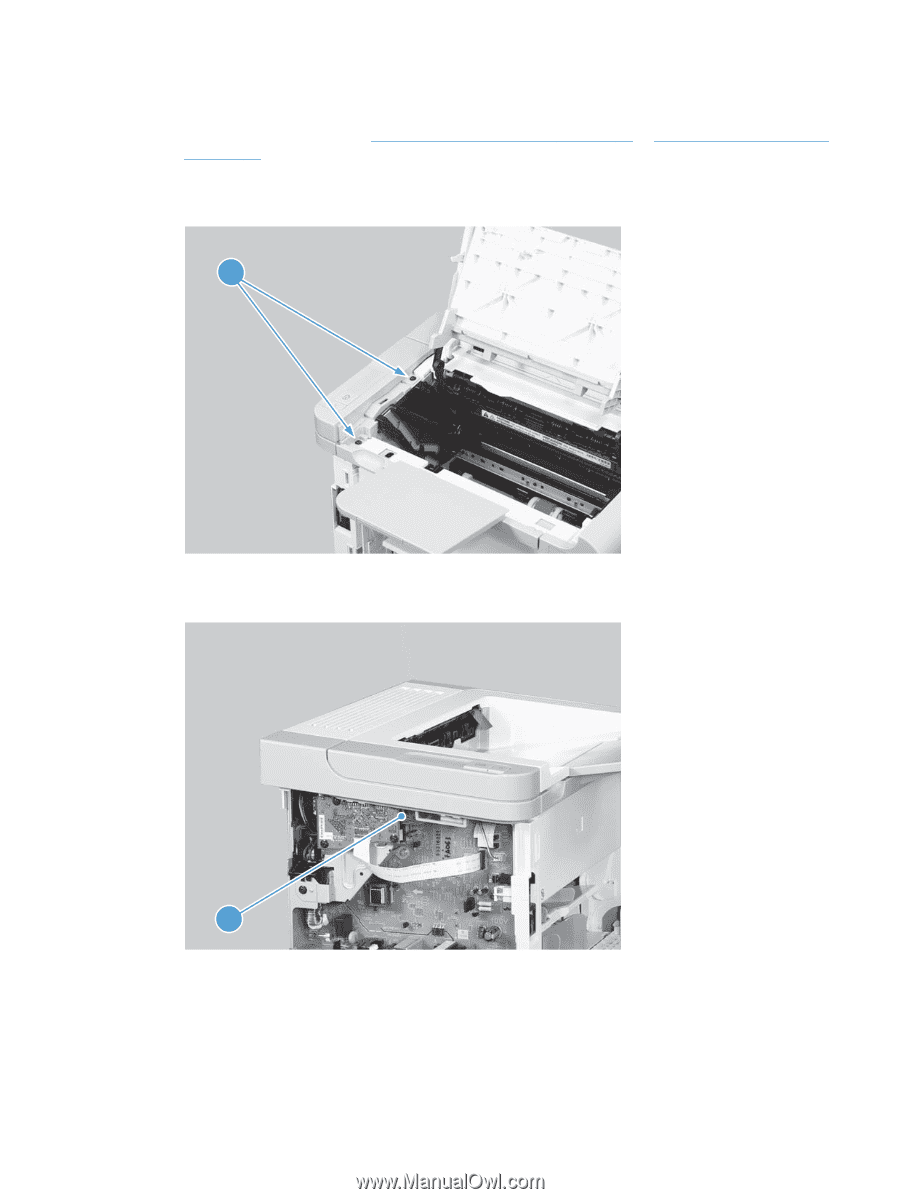
Control panel
1.
Remove the left cover. See
Left cover, simplex product
on page
45
or
Left cover, duplex product
on page
47
.
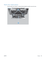
2.
Open the cartridge door, and then remove two screws (callout 1).
Figure 2-32
Remove the control panel (1 of 3)
1
3.
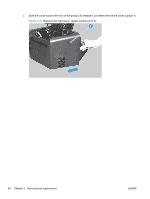
Disconnect one connector (callout 1).
Figure 2-33
Remove the control panel (2 of 3)
1
ENWW
Covers
59