HP LaserJet Pro P1606 HP LaserJet Professional P1560 and P1600 Series Printer - Page 85
Main assemblies, Formatter PCA,
 |
View all HP LaserJet Pro P1606 manuals
Add to My Manuals
Save this manual to your list of manuals |
Page 85 highlights
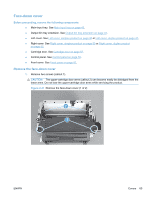
Main assemblies NOTE: Some photos in this section show components that might not be installed or removed from your product; however, the procedures for replacement and repair in this chapter are correct for your product. Formatter PCA 1. Remove the left cover. See Left cover, simplex product on page 45 or Left cover, duplex product on page 47. 2. Disconnect one FFC (callout 1) and one connector (callout 2). Figure 2-43 Remove the formatter PCA (1 of 2) 2 1 3. Remove three screws (callout 1), and then remove the formatter PCA. Figure 2-44 Remove the formatter PCA (2 of 2) 1 ENWW Main assemblies 67
-
 1
1 -
2
-
3
-
4
-
5
-
6
-
7
-
8
-
9
-
10
-
11
-
12
-
13
-
14
-
15
-
16
-
17
-
18
-
19
-
20
-
21
-
22
-
23
-
24
-
25
-
26
-
27
-
28
-
29
-
30
-
31
-
32
-
33
-
34
-
35
-
36
-
37
-
38
-
39
-
40
-
41
-
42
-
43
-
44
-
45
-
46
-
47
-
48
-
49
-
50
-
51
-
52
-
53
-
54
-
55
-
56
-
57
-
58
-
59
-
60
-
61
-
62
-
63
-
64
-
65
-
66
-
67
-
68
-
69
-
70
-
71
-
72
-
73
-
74
-
75
-
76
-
77
-
78
-
79
-
 80
80 -
 81
81 -
 82
82 -
 83
83 -
 84
84 -
 85
85 -
 86
86 -
 87
87 -
 88
88 -
 89
89 -
 90
90 -
91
-
92
-
93
-
94
-
95
-
96
-
97
-
98
-
99
-
100
-
101
-
102
-
103
-
104
-
105
-
106
-
107
-
108
-
109
-
110
-
111
-
112
-
113
-
114
-
115
-
116
-
117
-
118
-
119
-
120
-
121
-
122
-
123
-
124
-
125
-
126
-
127
-
128
-
129
-
130
-
131
-
132
-
133
-
134
-
135
-
136
-
137
-
138
-
139
-
140
-
141
-
142
-
143
-
144
-
145
-
146
-
147
-
148
-
149
-
150
-
151
-
152
-
153
-
154
-
155
-
156
-
157
-
158
-
159
-
160
-
161
-
162
-
163
-
164
-
165
-
166
-
167
-
168
-
169
-
170
-
171
-
172
-
173
-
174
-
175
-
176
-
177
-
178
-
179
-
180
-
181
-
182
-
183
-
184
-
185
-
186
-
187
-
188
-
189
-
190
-
191
-
192
-
193
-
194
-
195
-
196
-
197
-
198
-
199
-
200
-
201
-
202
-
203
-
204
-
205
-
206
-
207
-
208
-
209
-
210
-
211
-
212
-
213
-
214
-
215
-
216
-
217
-
218
-
219
-
220
-
221
-
222
-
223
-
224
-
225
-
226
 |
 |
Main assemblies
NOTE:
Some photos in this section show components that might not be installed or removed from
your product; however, the procedures for replacement and repair in this chapter are correct for your
product.
Formatter PCA
1.
Remove the left cover. See
Left cover, simplex product
on page
45
or
Left cover, duplex product
on page
47
.
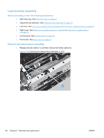
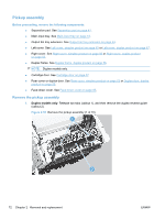
2.
Disconnect one FFC (callout 1) and one connector (callout 2).
Figure 2-43
Remove the formatter PCA (1 of 2)
1
2
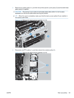
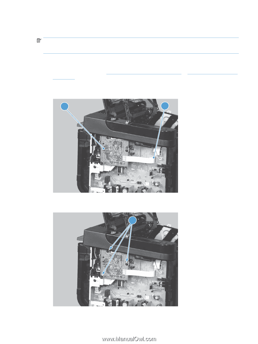
3.
Remove three screws (callout 1), and then remove the formatter PCA.
Figure 2-44
Remove the formatter PCA (2 of 2)
1
ENWW
Main assemblies
67