HP P6300 HP P6300/P6500 EVA Installation Guide (5697-2485, September 2013) - Page 29
Connecting cables and power cords, Overview, Cabling best practices, Connecting cables
 |
View all HP P6300 manuals
Add to My Manuals
Save this manual to your list of manuals |
Page 29 highlights
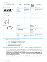
4 Connecting cables and power cords Overview NOTE: If you have ordered the factory integrated product, skip this chapter and go to "Turning on power" (page 32). To connect cables and power cords: 1. Read the cabling best practices. 2. Attach Fibre Channel, SAS, and/or LAN cables to controllers, drives, and servers. 3. Label all cables using the supplied cable labeling kit. 4. Plug in all power cables. Cabling best practices • Use the shortest possible cable between devices. Shorter cables are easier to manage and route along the back of the rack. In addition, shorter cables reduce the possibility of signal degradation that may occur over longer distances. • Gather the cables in the rear of the array to ensure that the cabling in the back of the rack system does not interfere with system operation or maintenance. Bind the cables loosely with cable ties and route the excess cables out of the way, along the side of the rack. When the cables are tied together and routed down the side of the rack, system components and indicators are easily visible and accessible. • Attach a label near both ends of each cable to identify the device connected to that cable. Include the device type, device name, port, or other information that you think will be helpful. • Use colored markers to color code both ends of each cable, to help you visually identify a particular cable without having to read or locate the label. • In multipath configurations, you may want to loosely bind the matching pair of cables connecting devices. Connecting cables To connect the EVA to the SAN, use standard Fibre Channel and/or SAS cables, observing the following caution for good cabling-handling practices. CAUTION: Use appropriate precautions when handling cables: • Touching the end of a cable can damage the cable or cause performance problems, including intermittent difficulties accessing the storage. • Whenever a cable is not connected, replace the protective covers on the ends of the cable. • Make certain that the cables are installed and supported so that no excess weight is placed on the connectors. This prevents damage to the connector and cable. Excess cable should be loosely coiled and tied out of the way, being careful not to coil the cable in a tight loop. • The minimum bend radius is 25 mm for 50, 62.5, and 9 micron fiber optic cable. The bend radius for the 0.5 meter SAS cable is 33 mm (1.3 inches); for the 2 meter SAS cable, it is 40.6 mm (1.6 inches). Connecting the array to the disk enclosures See "Cabling the P63x0/P65x0 EVA" (page 66) for examples of connecting the P63x0/P65x0 EVA to the disk enclosures. Overview 29
-
 1
1 -
2
-
3
-
4
-
5
-
6
-
7
-
8
-
9
-
10
-
11
-
12
-
13
-
14
-
15
-
16
-
17
-
18
-
19
-
20
-
21
-
22
-
23
-
 24
24 -
 25
25 -
 26
26 -
 27
27 -
 28
28 -
 29
29 -
 30
30 -
 31
31 -
 32
32 -
 33
33 -
 34
34 -
35
-
36
-
37
-
38
-
39
-
40
-
41
-
42
-
43
-
44
-
45
-
46
-
47
-
48
-
49
-
50
-
51
-
52
-
53
-
54
-
55
-
56
-
57
-
58
-
59
-
60
-
61
-
62
-
63
-
64
-
65
-
66
-
67
-
68
-
69
-
70
-
71
-
72
-
73
-
74
-
75
-
76
-
77
-
78
-
79
-
80
-
81
-
82
 |
 |
