HP P6300 HP P6300/P6500 EVA Installation Guide (5697-2485, September 2013) - Page 34
Verify the operating status of the Fibre Channel switches and adapters
 |
View all HP P6300 manuals
Add to My Manuals
Save this manual to your list of manuals |
Page 34 highlights
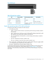
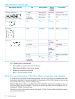
Table 5 Disk enclosure operating status Disk enclosure component LED Front UID module LEDs Power supply module 1. Health 2. Fault 3. UID (Unit identification) Status Startup condition Normal operating condition Blinking green Solid green Blinking amber Off Blinking blue Off Fault condition Off (No power) Blinking or Solid Amber Off Green Solid green Amber Fan module Status Solid green Solid green Blinking or solid amber I/O module 1. Port Link 2. Port Error 3. 7-segment display 4. Fault 5. Health 6. UID (Unit identification) Blinking green Blinking or Off solid green Off Solid amber A unique Off number representing the enclosure number Off Blinking or solid amber Solid green Off Off Off If LED patterns are not as expected: • Check cable connections between the devices. • Check the availability of your power source. • Review the installation procedures. • Remove and reinsert the module. Verify the operating status of the Fibre Channel switches and adapters To verify that your switches are operating properly, view the switch LEDs and compare them with the patterns described in the documentation for these devices. If the LEDs indicate a fault, see the documentation that came with the switch for help. Optional Step: If you will be using Fibre Channel to attach the array to your existing servers, you must install Fibre Channel adapters in those servers and test the Fibre Channel adapters prior to installing HP P6000 Command View. Ensure that you have the correct quantity and length of Fibre Channel cables available to attach your servers to the array. 34 Turning on power
-
 1
1 -
2
-
3
-
4
-
5
-
6
-
7
-
8
-
9
-
10
-
11
-
12
-
13
-
14
-
15
-
16
-
17
-
18
-
19
-
20
-
21
-
22
-
23
-
24
-
25
-
26
-
27
-
28
-
 29
29 -
 30
30 -
 31
31 -
 32
32 -
 33
33 -
 34
34 -
 35
35 -
 36
36 -
 37
37 -
 38
38 -
 39
39 -
40
-
41
-
42
-
43
-
44
-
45
-
46
-
47
-
48
-
49
-
50
-
51
-
52
-
53
-
54
-
55
-
56
-
57
-
58
-
59
-
60
-
61
-
62
-
63
-
64
-
65
-
66
-
67
-
68
-
69
-
70
-
71
-
72
-
73
-
74
-
75
-
76
-
77
-
78
-
79
-
80
-
81
-
82
 |
 |
