HP P6300 HP P6300/P6500 EVA Installation Guide (5697-2485, September 2013) - Page 30
Connecting the array to servers and switches, Labeling cables using labeling kit
 |
View all HP P6300 manuals
Add to My Manuals
Save this manual to your list of manuals |
Page 30 highlights
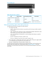
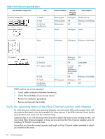
Connecting the array to servers and switches See "Cabling the P63x0/P65x0 EVA" (page 66) for examples of connecting servers and switches to the array in server-based management and array-based management configurations. Labeling cables using labeling kit A labeling kit is provided with the disk enclosure. Label both ends of each cable using the materials in the supplied labeling kit. Connecting the power cords WARNING! To reduce the risk of electric shock or damage to the equipment: • Do not disable the power cord grounding plug. The grounding plug is an important safety feature. • Plug the power cord into a grounded (earthed) electrical outlet that is easily accessible at all times. • To remove power to the equipment, unplug the power cord from the power supply. • Route the power cord so that it is not likely to be walked on or pinched by items placed against it. Pay particular attention to the plug, electrical outlet, and the point where the cord is attached to the array. To protect your system from power failure related downtime, each array ships with a redundant power supply. See Table 3 (page 31) to determine the best method for connecting your power supplies to your power source to eliminate downtime due to power-related failure. When connecting the power cables, use the power cables shipped with the array. After power is supplied to the array, the power supply automatically senses the input voltage and the power supply LED illuminates as solid amber. NOTE: If you ordered the AF092A rack, HP recommends that you use the 1.37 meter (minimum length) power cords. For accessibility, the PDU can be lowered out of the rack. As shown in Figure 19 (page 30), remove the mounting the screws (1) and pull down on the PDU (2) until it is in the fully lowered position (3). Figure 19 Accessing the PDU 30 Connecting cables and power cords
-
 1
1 -
2
-
3
-
4
-
5
-
6
-
7
-
8
-
9
-
10
-
11
-
12
-
13
-
14
-
15
-
16
-
17
-
18
-
19
-
20
-
21
-
22
-
23
-
24
-
 25
25 -
 26
26 -
 27
27 -
 28
28 -
 29
29 -
 30
30 -
 31
31 -
 32
32 -
 33
33 -
 34
34 -
 35
35 -
36
-
37
-
38
-
39
-
40
-
41
-
42
-
43
-
44
-
45
-
46
-
47
-
48
-
49
-
50
-
51
-
52
-
53
-
54
-
55
-
56
-
57
-
58
-
59
-
60
-
61
-
62
-
63
-
64
-
65
-
66
-
67
-
68
-
69
-
70
-
71
-
72
-
73
-
74
-
75
-
76
-
77
-
78
-
79
-
80
-
81
-
82
 |
 |
