HP P6300 HP P6300/P6500 EVA Installation Guide (5697-2485, September 2013) - Page 33
Verify the operating status of the disk enclosures, I/O module status LEDs
 |
View all HP P6300 manuals
Add to My Manuals
Save this manual to your list of manuals |
Page 33 highlights
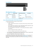
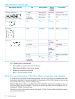
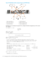
Figure 20 LED panel Table 4 LED panel status conditions LED Startup condition 1. UID (Unit identification) Blinking blue 2. Health Blinking green 3. Fault Blinking amber 4. Link status Blinking amber Normal operating condition Fault condition Off Off Solid green Off Off Blinking or solid amber Solid green - successfully Amber - host connection lost connected to host Verify the operating status of the disk enclosures The following status LEDs are located on the disk enclosure: • I/O module status LEDs: ◦ Health-indicates that the enclosure is powered up and functioning normally. Located in front and rear. ◦ Fault-indicates when a fault has occurred. A blinking LED indicates a lesser fault; a solid LED indicates a more serious fault. Located in front and rear. ◦ UID-Unit identification, this blue LED is on when locating a disk enclosure. Located in front and rear. ◦ Port link-indicates the link status. Located in rear. ◦ Port error-indicates if a port error has occurred. Located in rear. • Power supply status-indicates status of the power supply module. If the power supply module is not connected properly, the LED will be off. Located in rear. • Fan status-indicates status of the fan module. Located in rear. To verify that the disk enclosures and disk drives are operating properly, view the enclosure and disk drive LEDs and compare them with the patterns shown in Table 5 (page 34). For more information on the disk enclosure status LEDs, see the HP P63x0/P65x0 Enterprise Virtual Array User Guide. Verify the operating status of the disk enclosures 33
-
 1
1 -
2
-
3
-
4
-
5
-
6
-
7
-
8
-
9
-
10
-
11
-
12
-
13
-
14
-
15
-
16
-
17
-
18
-
19
-
20
-
21
-
22
-
23
-
24
-
25
-
26
-
27
-
 28
28 -
 29
29 -
 30
30 -
 31
31 -
 32
32 -
 33
33 -
 34
34 -
 35
35 -
 36
36 -
 37
37 -
 38
38 -
39
-
40
-
41
-
42
-
43
-
44
-
45
-
46
-
47
-
48
-
49
-
50
-
51
-
52
-
53
-
54
-
55
-
56
-
57
-
58
-
59
-
60
-
61
-
62
-
63
-
64
-
65
-
66
-
67
-
68
-
69
-
70
-
71
-
72
-
73
-
74
-
75
-
76
-
77
-
78
-
79
-
80
-
81
-
82
 |
 |
