HP Pro 6305 Maintenance and Service Guide HP Compaq Pro 6305 Microtower Busine - Page 115
System Board Connections
 |
View all HP Pro 6305 manuals
Add to My Manuals
Save this manual to your list of manuals |
Page 115 highlights
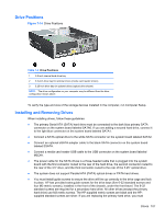
11. Replace the computer access panel. 12. If the computer was on a stand, replace the stand. 13. Reconnect the power cord and turn on the computer. 14. Lock any security devices that were disengaged when the access panel was removed. 15. Reconfigure the computer, if necessary. System Board Connections Refer to the following illustration and table to identify the system board connectors for your model. Figure 7-13 System Board Connections Table 7-1 System Board Connections No. System Board Connector System Board Label 1 DIMM4 (Channel A) DIMM4 2 DIMM3 (Channel A) DIMM3 3 DIMM2 (Channel B) DIMM2 4 DIMM1 (Channel B) DIMM1 5 eSATA ESATA 6 SATA 2.0 SATA2 7 Power SATAS_PWR2 8 Power SATAS_PWR1 9 SATA 3.0 SATA1 10 SATA 3.0 SATA0 11 Serial Port COMB 12 Parallel Port PAR 13 USB MEDIA2 Color white black white black black white black black light blue dark blue black black black Component Memory Module Memory Module Memory Module Memory Module eSATA Adapter Cable 1st Optical Drive (unused) SATA Optical and Hard Drives 2nd Hard Drive 1st Hard Drive Serial Port Parallel Port Second Media Card Reader System Board Connections 105
-
 1
1 -
2
-
3
-
4
-
5
-
6
-
7
-
8
-
9
-
10
-
11
-
12
-
13
-
14
-
15
-
16
-
17
-
18
-
19
-
20
-
21
-
22
-
23
-
24
-
25
-
26
-
27
-
28
-
29
-
30
-
31
-
32
-
33
-
34
-
35
-
36
-
37
-
38
-
39
-
40
-
41
-
42
-
43
-
44
-
45
-
46
-
47
-
48
-
49
-
50
-
51
-
52
-
53
-
54
-
55
-
56
-
57
-
58
-
59
-
60
-
61
-
62
-
63
-
64
-
65
-
66
-
67
-
68
-
69
-
70
-
71
-
72
-
73
-
74
-
75
-
76
-
77
-
78
-
79
-
80
-
81
-
82
-
83
-
84
-
85
-
86
-
87
-
88
-
89
-
90
-
91
-
92
-
93
-
94
-
95
-
96
-
97
-
98
-
99
-
100
-
101
-
102
-
103
-
104
-
105
-
106
-
107
-
108
-
109
-
 110
110 -
 111
111 -
 112
112 -
 113
113 -
 114
114 -
 115
115 -
 116
116 -
 117
117 -
 118
118 -
 119
119 -
 120
120 -
121
-
122
-
123
-
124
-
125
-
126
-
127
-
128
-
129
-
130
-
131
-
132
-
133
-
134
-
135
-
136
-
137
-
138
-
139
-
140
-
141
-
142
-
143
-
144
-
145
-
146
-
147
-
148
-
149
-
150
-
151
-
152
-
153
-
154
-
155
-
156
-
157
-
158
-
159
-
160
-
161
-
162
-
163
-
164
-
165
-
166
-
167
-
168
-
169
-
170
-
171
-
172
-
173
-
174
-
175
-
176
-
177
-
178
-
179
-
180
-
181
-
182
-
183
-
184
-
185
-
186
-
187
-
188
-
189
-
190
-
191
-
192
-
193
-
194
-
195
-
196
-
197
-
198
-
199
-
200
-
201
-
202
-
203
-
204
-
205
-
206
-
207
-
208
-
209
-
210
-
211
-
212
-
213
-
214
-
215
-
216
-
217
 |
 |
