HP Pro 6305 Maintenance and Service Guide HP Compaq Pro 6305 Microtower Busine - Page 139
Heat sink, Preparation for Disassembly, on Access Panel, Fan duct, Front Fan Assembly
 |
View all HP Pro 6305 manuals
Add to My Manuals
Save this manual to your list of manuals |
Page 139 highlights
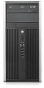
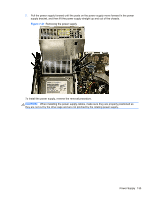
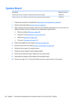
Heat sink Description Heat sink Spare part number 645326-001 CAUTION: The bond between the heat sink and the processor may be very tight. If the computer will power on, before removing the heat sink, turn on the computer until it warms the heat sink. Warming the heat sink lessens the bond between the heat sink and the processor, thereby making separating them easier. Make sure not to pull the processor out of the socket when you lift the heat sink, especially if you cannot warm the heat sink prior to removal. Inadvertently removing the processor can damage the pins. The heat sink is secured atop the processor with four captive Torx screws. The heat sink does not include a fan. 1. Prepare the computer for disassembly (Preparation for Disassembly on page 92). 2. Remove the access panel (Access Panel on page 93). 3. Remove the fan duct (Fan duct on page 122). 4. Remove the front fan (Front Fan Assembly on page 123). 5. Loosen the four captive screws that secure the heat sink to the system board tray. CAUTION: Heat sink retaining screws should be removed in diagonally opposite pairs (as in an X) to even the downward forces on the processor. This is especially important as the pins on the socket are very fragile and any damage to them may require replacing the system board. Figure 7-44 Loosening the heat sink screws Heat sink 129
-
 1
1 -
2
-
3
-
4
-
5
-
6
-
7
-
8
-
9
-
10
-
11
-
12
-
13
-
14
-
15
-
16
-
17
-
18
-
19
-
20
-
21
-
22
-
23
-
24
-
25
-
26
-
27
-
28
-
29
-
30
-
31
-
32
-
33
-
34
-
35
-
36
-
37
-
38
-
39
-
40
-
41
-
42
-
43
-
44
-
45
-
46
-
47
-
48
-
49
-
50
-
51
-
52
-
53
-
54
-
55
-
56
-
57
-
58
-
59
-
60
-
61
-
62
-
63
-
64
-
65
-
66
-
67
-
68
-
69
-
70
-
71
-
72
-
73
-
74
-
75
-
76
-
77
-
78
-
79
-
80
-
81
-
82
-
83
-
84
-
85
-
86
-
87
-
88
-
89
-
90
-
91
-
92
-
93
-
94
-
95
-
96
-
97
-
98
-
99
-
100
-
101
-
102
-
103
-
104
-
105
-
106
-
107
-
108
-
109
-
110
-
111
-
112
-
113
-
114
-
115
-
116
-
117
-
118
-
119
-
120
-
121
-
122
-
123
-
124
-
125
-
126
-
127
-
128
-
129
-
130
-
131
-
132
-
133
-
 134
134 -
 135
135 -
 136
136 -
 137
137 -
 138
138 -
 139
139 -
 140
140 -
 141
141 -
 142
142 -
 143
143 -
 144
144 -
145
-
146
-
147
-
148
-
149
-
150
-
151
-
152
-
153
-
154
-
155
-
156
-
157
-
158
-
159
-
160
-
161
-
162
-
163
-
164
-
165
-
166
-
167
-
168
-
169
-
170
-
171
-
172
-
173
-
174
-
175
-
176
-
177
-
178
-
179
-
180
-
181
-
182
-
183
-
184
-
185
-
186
-
187
-
188
-
189
-
190
-
191
-
192
-
193
-
194
-
195
-
196
-
197
-
198
-
199
-
200
-
201
-
202
-
203
-
204
-
205
-
206
-
207
-
208
-
209
-
210
-
211
-
212
-
213
-
214
-
215
-
216
-
217
 |
 |
