HP Pro 6305 Maintenance and Service Guide HP Compaq Pro 6305 Microtower Busine - Page 81
Installing a Hard Drive into an Internal Drive Bay,
 |
View all HP Pro 6305 manuals
Add to My Manuals
Save this manual to your list of manuals |
Page 81 highlights
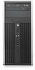
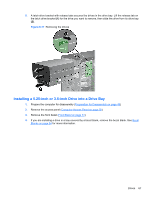
Installing a Hard Drive into an Internal Drive Bay NOTE: The system does not support Parallel ATA (PATA) hard drives. 1. Prepare the computer for disassembly (Preparation for Disassembly on page 49) 2. Remove the access panel (Computer Access Panel on page 50) 3. Install guide screws on the sides of the drive. If you are installing a 2.5-inch drive, you must install the drive in an adapter bracket. NOTE: The hard drive uses 6-32 isolation mounting guide screws. Four extra guide screws are installed on the exterior of the hard drive bays. The HP-supplied isolation mounting guide screws are silver and blue. Refer to Drives on page 63 for an illustration of the extra 6-32 isolation mounting guide screws location. If you are replacing a drive, transfer the guides screws from the old drive to the new one. ● If you are installing a 3.5-inch hard drive, install four isolation mounting guide screws (two on each side of the drive). Figure 6-23 Installing Isolation Mounting Guide Screws in a 3.5-inch Drive ● If you are installing a 2.5-inch hard drive: ◦ Slide the drive into the bay adapter bracket, ensuring the connector on the drive is fully inserted into the connector on the adapter bracket. Figure 6-24 Sliding the 2.5-inch Drive in the Adapter Bracket Drives 71
-
 1
1 -
2
-
3
-
4
-
5
-
6
-
7
-
8
-
9
-
10
-
11
-
12
-
13
-
14
-
15
-
16
-
17
-
18
-
19
-
20
-
21
-
22
-
23
-
24
-
25
-
26
-
27
-
28
-
29
-
30
-
31
-
32
-
33
-
34
-
35
-
36
-
37
-
38
-
39
-
40
-
41
-
42
-
43
-
44
-
45
-
46
-
47
-
48
-
49
-
50
-
51
-
52
-
53
-
54
-
55
-
56
-
57
-
58
-
59
-
60
-
61
-
62
-
63
-
64
-
65
-
66
-
67
-
68
-
69
-
70
-
71
-
72
-
73
-
74
-
75
-
 76
76 -
 77
77 -
 78
78 -
 79
79 -
 80
80 -
 81
81 -
 82
82 -
 83
83 -
 84
84 -
 85
85 -
 86
86 -
87
-
88
-
89
-
90
-
91
-
92
-
93
-
94
-
95
-
96
-
97
-
98
-
99
-
100
-
101
-
102
-
103
-
104
-
105
-
106
-
107
-
108
-
109
-
110
-
111
-
112
-
113
-
114
-
115
-
116
-
117
-
118
-
119
-
120
-
121
-
122
-
123
-
124
-
125
-
126
-
127
-
128
-
129
-
130
-
131
-
132
-
133
-
134
-
135
-
136
-
137
-
138
-
139
-
140
-
141
-
142
-
143
-
144
-
145
-
146
-
147
-
148
-
149
-
150
-
151
-
152
-
153
-
154
-
155
-
156
-
157
-
158
-
159
-
160
-
161
-
162
-
163
-
164
-
165
-
166
-
167
-
168
-
169
-
170
-
171
-
172
-
173
-
174
-
175
-
176
-
177
-
178
-
179
-
180
-
181
-
182
-
183
-
184
-
185
-
186
-
187
-
188
-
189
-
190
-
191
-
192
-
193
-
194
-
195
-
196
-
197
-
198
-
199
-
200
-
201
-
202
-
203
-
204
-
205
-
206
-
207
-
208
-
209
-
210
-
211
-
212
-
213
-
214
-
215
-
216
-
217
 |
 |
