HP Pro 6305 Maintenance and Service Guide HP Compaq Pro 6305 Microtower Busine - Page 136
Front I/O, Power Switch Assembly
 |
View all HP Pro 6305 manuals
Add to My Manuals
Save this manual to your list of manuals |
Page 136 highlights
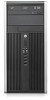
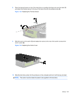
Front I/O, Power Switch Assembly Description Front I/O and power switch assembly Spare part number 636926-001 The front I/O and power switch/LEDs is one assembly, attached to the front of the chassis. Push the assembly into the chassis to remove. 1. Prepare the computer for disassembly (Preparation for Disassembly on page 92). 2. Remove the access panel (Access Panel on page 93). 3. Remove the front bezel (Front Bezel on page 94). 4. Remove the chassis fan (Front Fan Assembly on page 123). 5. Rotate the drive cage to its upright position. 6. Disconnect the four cables from the system board as follows: ● Yellow connector labeled FRONT_USB ● Green connector labeled FRONT_USB2 ● Blue connector labeled FRONT AUD ● Black connector labeled PB/LED Figure 7-41 Disconnecting the front I/O, power switch/LED assembly cables 7. Remove the Torx T15 screw (1) that secures the assembly to the front of the chassis. 126 Chapter 7 Removal and Replacement Procedures Small Form Factor (SFF) Chassis
-
 1
1 -
2
-
3
-
4
-
5
-
6
-
7
-
8
-
9
-
10
-
11
-
12
-
13
-
14
-
15
-
16
-
17
-
18
-
19
-
20
-
21
-
22
-
23
-
24
-
25
-
26
-
27
-
28
-
29
-
30
-
31
-
32
-
33
-
34
-
35
-
36
-
37
-
38
-
39
-
40
-
41
-
42
-
43
-
44
-
45
-
46
-
47
-
48
-
49
-
50
-
51
-
52
-
53
-
54
-
55
-
56
-
57
-
58
-
59
-
60
-
61
-
62
-
63
-
64
-
65
-
66
-
67
-
68
-
69
-
70
-
71
-
72
-
73
-
74
-
75
-
76
-
77
-
78
-
79
-
80
-
81
-
82
-
83
-
84
-
85
-
86
-
87
-
88
-
89
-
90
-
91
-
92
-
93
-
94
-
95
-
96
-
97
-
98
-
99
-
100
-
101
-
102
-
103
-
104
-
105
-
106
-
107
-
108
-
109
-
110
-
111
-
112
-
113
-
114
-
115
-
116
-
117
-
118
-
119
-
120
-
121
-
122
-
123
-
124
-
125
-
126
-
127
-
128
-
129
-
130
-
 131
131 -
 132
132 -
 133
133 -
 134
134 -
 135
135 -
 136
136 -
 137
137 -
 138
138 -
 139
139 -
 140
140 -
 141
141 -
142
-
143
-
144
-
145
-
146
-
147
-
148
-
149
-
150
-
151
-
152
-
153
-
154
-
155
-
156
-
157
-
158
-
159
-
160
-
161
-
162
-
163
-
164
-
165
-
166
-
167
-
168
-
169
-
170
-
171
-
172
-
173
-
174
-
175
-
176
-
177
-
178
-
179
-
180
-
181
-
182
-
183
-
184
-
185
-
186
-
187
-
188
-
189
-
190
-
191
-
192
-
193
-
194
-
195
-
196
-
197
-
198
-
199
-
200
-
201
-
202
-
203
-
204
-
205
-
206
-
207
-
208
-
209
-
210
-
211
-
212
-
213
-
214
-
215
-
216
-
217
 |
 |
