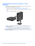
HP Pro 6305 Maintenance and Service Guide HP Compaq Pro 6305 Microtower Busine - Page 144
Preparation for Disassembly, on Access Panel, Memory, Expansion Card, Heat sink, Processor
 |
View all HP Pro 6305 manuals
Add to My Manuals
Save this manual to your list of manuals |
Page 144 highlights
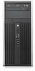
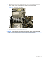
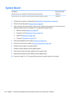
System Board Description System board for use in Windows 7 models (includes thermal material) System board for use in NetClone models (includes replacement thermal material) Spare part number 703596-001 710096-001 1. Prepare the computer for disassembly (Preparation for Disassembly on page 92). 2. Remove the access panel (Access Panel on page 93). 3. When replacing the system board, make sure the following components are removed from the defective system board and installed on the replacement system board: ● Memory modules (Memory on page 98) ● Expansion cards (Expansion Card on page 101) ● Heat sink (Heat sink on page 129) ● Processor (Processor on page 131) 4. Remove the baffle from the chassis (Fan duct on page 122). 5. Remove the fan from the chassis (Front Fan Assembly on page 123). 6. Rotate the drive cage to its upright position. 7. Rotate the power supply to its full upright position. 8. Disconnect all data and power cables from the system board. 9. Disconnect the balance of the cables from the system board. 10. Remove the eight Torx T15 screws (1) that secure the system board to the chassis. 134 Chapter 7 Removal and Replacement Procedures Small Form Factor (SFF) Chassis
-
 1
1 -
2
-
3
-
4
-
5
-
6
-
7
-
8
-
9
-
10
-
11
-
12
-
13
-
14
-
15
-
16
-
17
-
18
-
19
-
20
-
21
-
22
-
23
-
24
-
25
-
26
-
27
-
28
-
29
-
30
-
31
-
32
-
33
-
34
-
35
-
36
-
37
-
38
-
39
-
40
-
41
-
42
-
43
-
44
-
45
-
46
-
47
-
48
-
49
-
50
-
51
-
52
-
53
-
54
-
55
-
56
-
57
-
58
-
59
-
60
-
61
-
62
-
63
-
64
-
65
-
66
-
67
-
68
-
69
-
70
-
71
-
72
-
73
-
74
-
75
-
76
-
77
-
78
-
79
-
80
-
81
-
82
-
83
-
84
-
85
-
86
-
87
-
88
-
89
-
90
-
91
-
92
-
93
-
94
-
95
-
96
-
97
-
98
-
99
-
100
-
101
-
102
-
103
-
104
-
105
-
106
-
107
-
108
-
109
-
110
-
111
-
112
-
113
-
114
-
115
-
116
-
117
-
118
-
119
-
120
-
121
-
122
-
123
-
124
-
125
-
126
-
127
-
128
-
129
-
130
-
131
-
132
-
133
-
134
-
135
-
136
-
137
-
138
-
 139
139 -
 140
140 -
 141
141 -
 142
142 -
 143
143 -
 144
144 -
 145
145 -
 146
146 -
 147
147 -
 148
148 -
 149
149 -
150
-
151
-
152
-
153
-
154
-
155
-
156
-
157
-
158
-
159
-
160
-
161
-
162
-
163
-
164
-
165
-
166
-
167
-
168
-
169
-
170
-
171
-
172
-
173
-
174
-
175
-
176
-
177
-
178
-
179
-
180
-
181
-
182
-
183
-
184
-
185
-
186
-
187
-
188
-
189
-
190
-
191
-
192
-
193
-
194
-
195
-
196
-
197
-
198
-
199
-
200
-
201
-
202
-
203
-
204
-
205
-
206
-
207
-
208
-
209
-
210
-
211
-
212
-
213
-
214
-
215
-
216
-
217
 |
 |
