HP Pro 6305 Maintenance and Service Guide HP Compaq Pro 6305 Microtower Busine - Page 77
Installing a 5.25-inch or 3.5-inch Drive into a Drive Bay,
 |
View all HP Pro 6305 manuals
Add to My Manuals
Save this manual to your list of manuals |
Page 77 highlights
5. A latch drive bracket with release tabs secures the drives in the drive bay. Lift the release tab on the latch drive bracket (1) for the drive you want to remove, then slide the drive from its drive bay (2). Figure 6-17 Removing the Drives Installing a 5.25-inch or 3.5-inch Drive into a Drive Bay 1. Prepare the computer for disassembly (Preparation for Disassembly on page 49) 2. Remove the access panel (Computer Access Panel on page 50) 3. Remove the front bezel (Front Bezel on page 51) 4. If you are installing a drive in a bay covered by a bezel blank, remove the bezel blank. See Bezel Blanks on page 54 for more information. Drives 67
-
 1
1 -
2
-
3
-
4
-
5
-
6
-
7
-
8
-
9
-
10
-
11
-
12
-
13
-
14
-
15
-
16
-
17
-
18
-
19
-
20
-
21
-
22
-
23
-
24
-
25
-
26
-
27
-
28
-
29
-
30
-
31
-
32
-
33
-
34
-
35
-
36
-
37
-
38
-
39
-
40
-
41
-
42
-
43
-
44
-
45
-
46
-
47
-
48
-
49
-
50
-
51
-
52
-
53
-
54
-
55
-
56
-
57
-
58
-
59
-
60
-
61
-
62
-
63
-
64
-
65
-
66
-
67
-
68
-
69
-
70
-
71
-
 72
72 -
 73
73 -
 74
74 -
 75
75 -
 76
76 -
 77
77 -
 78
78 -
 79
79 -
 80
80 -
 81
81 -
 82
82 -
83
-
84
-
85
-
86
-
87
-
88
-
89
-
90
-
91
-
92
-
93
-
94
-
95
-
96
-
97
-
98
-
99
-
100
-
101
-
102
-
103
-
104
-
105
-
106
-
107
-
108
-
109
-
110
-
111
-
112
-
113
-
114
-
115
-
116
-
117
-
118
-
119
-
120
-
121
-
122
-
123
-
124
-
125
-
126
-
127
-
128
-
129
-
130
-
131
-
132
-
133
-
134
-
135
-
136
-
137
-
138
-
139
-
140
-
141
-
142
-
143
-
144
-
145
-
146
-
147
-
148
-
149
-
150
-
151
-
152
-
153
-
154
-
155
-
156
-
157
-
158
-
159
-
160
-
161
-
162
-
163
-
164
-
165
-
166
-
167
-
168
-
169
-
170
-
171
-
172
-
173
-
174
-
175
-
176
-
177
-
178
-
179
-
180
-
181
-
182
-
183
-
184
-
185
-
186
-
187
-
188
-
189
-
190
-
191
-
192
-
193
-
194
-
195
-
196
-
197
-
198
-
199
-
200
-
201
-
202
-
203
-
204
-
205
-
206
-
207
-
208
-
209
-
210
-
211
-
212
-
213
-
214
-
215
-
216
-
217
 |
 |
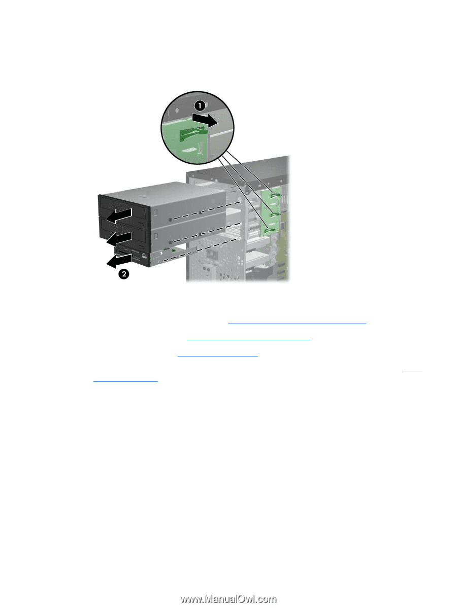
5.
A latch drive bracket with release tabs secures the drives in the drive bay. Lift the release tab on
the latch drive bracket
(1)
for the drive you want to remove, then slide the drive from its drive bay
(2)
.
Figure 6-17
Removing the Drives
Installing a 5.25-inch or 3.5-inch Drive into a Drive Bay
1.
Prepare the computer for disassembly (
Preparation for Disassembly
on page
49
)
2.
Remove the access panel (
Computer Access Panel
on page
50
)
3.
Remove the front bezel (
Front Bezel
on page
51
)
4.
If you are installing a drive in a bay covered by a bezel blank, remove the bezel blank. See
Bezel
Blanks
on page
54
for more information.
Drives
67