HP Pro 6305 Maintenance and Service Guide HP Compaq Pro 6305 Microtower Busine - Page 80
Removing a Hard Drive from a Drive Bay, System Board Connections, on Preparation for Disassembly
 |
View all HP Pro 6305 manuals
Add to My Manuals
Save this manual to your list of manuals |
Page 80 highlights
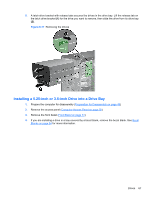
8. If installing a new drive, connect the opposite end of the data cable to the appropriate system board connector. NOTE: If you are installing a new SATA optical drive, connect the data cable for the first optical drive to the white SATA connector on the system board labeled SATA2. Connect the data cable for a second optical drive to the black SATA connector on the system board labeled ESATA. If the ESATA connector is already populated, connect the second optical drive to the light blue connector labeled SATA1. Refer to System Board Connections on page 62 for an illustration of the system board drive connectors. 9. Replace the front bezel and computer access panel. 10. Reconnect the power cord and any external devices, then turn on the computer. 11. Lock any security devices that were disengaged when the access panel was removed. Removing a Hard Drive from a Drive Bay NOTE: Before you remove the old hard drive, be sure to back up the data from the old hard drive so that you can transfer the data to the new hard drive. 1. Prepare the computer for disassembly (Preparation for Disassembly on page 49) 2. Remove the access panel (Computer Access Panel on page 50) 3. Disconnect the power cable and data cable from the back of the hard drive. 4. Release the drive by pulling the release tab away from the drive (1) and sliding the drive out of the bay (2). Figure 6-22 Removing a Hard Drive 5. Remove the four guide screws (two on each side) from the old drive. You will need these screws to install a new drive. 70 Chapter 6 Removal and Replacement Procedures Microtower (MT) Chassis
-
 1
1 -
2
-
3
-
4
-
5
-
6
-
7
-
8
-
9
-
10
-
11
-
12
-
13
-
14
-
15
-
16
-
17
-
18
-
19
-
20
-
21
-
22
-
23
-
24
-
25
-
26
-
27
-
28
-
29
-
30
-
31
-
32
-
33
-
34
-
35
-
36
-
37
-
38
-
39
-
40
-
41
-
42
-
43
-
44
-
45
-
46
-
47
-
48
-
49
-
50
-
51
-
52
-
53
-
54
-
55
-
56
-
57
-
58
-
59
-
60
-
61
-
62
-
63
-
64
-
65
-
66
-
67
-
68
-
69
-
70
-
71
-
72
-
73
-
74
-
 75
75 -
 76
76 -
 77
77 -
 78
78 -
 79
79 -
 80
80 -
 81
81 -
 82
82 -
 83
83 -
 84
84 -
 85
85 -
86
-
87
-
88
-
89
-
90
-
91
-
92
-
93
-
94
-
95
-
96
-
97
-
98
-
99
-
100
-
101
-
102
-
103
-
104
-
105
-
106
-
107
-
108
-
109
-
110
-
111
-
112
-
113
-
114
-
115
-
116
-
117
-
118
-
119
-
120
-
121
-
122
-
123
-
124
-
125
-
126
-
127
-
128
-
129
-
130
-
131
-
132
-
133
-
134
-
135
-
136
-
137
-
138
-
139
-
140
-
141
-
142
-
143
-
144
-
145
-
146
-
147
-
148
-
149
-
150
-
151
-
152
-
153
-
154
-
155
-
156
-
157
-
158
-
159
-
160
-
161
-
162
-
163
-
164
-
165
-
166
-
167
-
168
-
169
-
170
-
171
-
172
-
173
-
174
-
175
-
176
-
177
-
178
-
179
-
180
-
181
-
182
-
183
-
184
-
185
-
186
-
187
-
188
-
189
-
190
-
191
-
192
-
193
-
194
-
195
-
196
-
197
-
198
-
199
-
200
-
201
-
202
-
203
-
204
-
205
-
206
-
207
-
208
-
209
-
210
-
211
-
212
-
213
-
214
-
215
-
216
-
217
 |
 |
