HP ProBook 6550b HP ProBook 6455b, 6555b, 6450b,and 6550b Notebook PCs - Maint - Page 103
that secure the optical drive bracket to the, optical drive.
 |
View all HP ProBook 6550b manuals
Add to My Manuals
Save this manual to your list of manuals |
Page 103 highlights
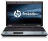
4. Remove the optical drive (3) from the optical drive bay. 5. If it is necessary to replace the optical drive bracket, follow these steps: a. Position the optical drive with the rear toward you. b. Remove the three Phillips PM2.0×3.0 screws (1) that secure the optical drive bracket to the optical drive. c. Remove the optical drive bracket (2). Reverse this procedure to reassemble and install the optical drive. Component replacement procedures 95
-
 1
1 -
2
-
3
-
4
-
5
-
6
-
7
-
8
-
9
-
10
-
11
-
12
-
13
-
14
-
15
-
16
-
17
-
18
-
19
-
20
-
21
-
22
-
23
-
24
-
25
-
26
-
27
-
28
-
29
-
30
-
31
-
32
-
33
-
34
-
35
-
36
-
37
-
38
-
39
-
40
-
41
-
42
-
43
-
44
-
45
-
46
-
47
-
48
-
49
-
50
-
51
-
52
-
53
-
54
-
55
-
56
-
57
-
58
-
59
-
60
-
61
-
62
-
63
-
64
-
65
-
66
-
67
-
68
-
69
-
70
-
71
-
72
-
73
-
74
-
75
-
76
-
77
-
78
-
79
-
80
-
81
-
82
-
83
-
84
-
85
-
86
-
87
-
88
-
89
-
90
-
91
-
92
-
93
-
94
-
95
-
96
-
97
-
 98
98 -
 99
99 -
 100
100 -
 101
101 -
 102
102 -
 103
103 -
 104
104 -
 105
105 -
 106
106 -
 107
107 -
 108
108 -
109
-
110
-
111
-
112
-
113
-
114
-
115
-
116
-
117
-
118
-
119
-
120
-
121
-
122
-
123
-
124
-
125
-
126
-
127
-
128
-
129
-
130
-
131
-
132
-
133
-
134
-
135
-
136
-
137
-
138
-
139
-
140
-
141
-
142
-
143
-
144
-
145
-
146
-
147
-
148
-
149
-
150
-
151
-
152
-
153
-
154
-
155
-
156
-
157
-
158
-
159
-
160
-
161
-
162
-
163
-
164
-
165
-
166
-
167
-
168
-
169
-
170
-
171
-
172
-
173
-
174
-
175
-
176
-
177
-
178
-
179
-
180
-
181
-
182
-
183
-
184
-
185
-
186
-
187
-
188
-
189
-
190
-
191
-
192
-
193
-
194
-
195
-
196
-
197
-
198
-
199
-
200
-
201
-
202
-
203
-
204
-
205
-
206
-
207
-
208
-
209
-
210
-
211
-
212
-
213
-
214
-
215
-
216
-
217
-
218
-
219
 |
 |

4.
Remove the optical drive
(3)
from the optical drive bay.
5.
If it is necessary to replace the optical drive bracket, follow these steps:
a.
Position the optical drive with the rear toward you.
b.
Remove the three Phillips PM2.0×3.0 screws
(1)
that secure the optical drive bracket to the
optical drive.
c.
Remove the optical drive bracket
(2)
.
Reverse this procedure to reassemble and install the optical drive.
Component replacement procedures
95