HP ProBook 6550b HP ProBook 6455b, 6555b, 6450b,and 6550b Notebook PCs - Maint - Page 121
Heat sink, captive screws - memory locator
 |
View all HP ProBook 6550b manuals
Add to My Manuals
Save this manual to your list of manuals |
Page 121 highlights
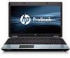
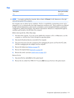
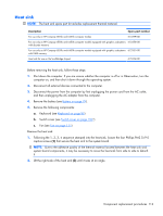
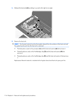
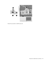
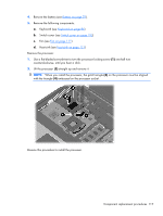
Heat sink NOTE: The heat sink spare part kit includes replacement thermal material. Description Spare part number For use only on HP Compaq 6555b and 6455b computer models 613399-001 For use only on HP Compaq 6550b and 6450b computer models equipped with graphics subsystems 613350-001 with discrete memory For use only on HP Compaq 6550b and 6450b computer models equipped with graphics subsystems 613351-001 with UMA memory Heat sink for use on the SouthBridge chipset 615956-001 Before removing the heat sink, follow these steps: 1. Shut down the computer. If you are unsure whether the computer is off or in Hibernation, turn the computer on, and then shut it down through the operating system. 2. Disconnect all external devices connected to the computer. 3. Disconnect the power from the computer by first unplugging the power cord from the AC outlet, and then unplugging the AC adapter from the computer. 4. Remove the battery (see Battery on page 79). 5. Remove the following components: a. Keyboard (see Keyboard on page 96) b. Switch cover (see Switch cover on page 103") c. Fan (see Fan on page 111) Remove the heat sink: 1. Following the 1, 2, 3, 4 sequence stamped into the heat sink, loosen the four Phillips PM2.5×9.0 captive screws (1) that secure the heat sink to the system board. NOTE: Due to the adhesive quality of the thermal material located between the heat sink and system board components, it may be necessary to move the heat sink from side to side to detach it. 2. Lift the right side of the heat sink (2) until it rests at an angle. Component replacement procedures 113
-
 1
1 -
2
-
3
-
4
-
5
-
6
-
7
-
8
-
9
-
10
-
11
-
12
-
13
-
14
-
15
-
16
-
17
-
18
-
19
-
20
-
21
-
22
-
23
-
24
-
25
-
26
-
27
-
28
-
29
-
30
-
31
-
32
-
33
-
34
-
35
-
36
-
37
-
38
-
39
-
40
-
41
-
42
-
43
-
44
-
45
-
46
-
47
-
48
-
49
-
50
-
51
-
52
-
53
-
54
-
55
-
56
-
57
-
58
-
59
-
60
-
61
-
62
-
63
-
64
-
65
-
66
-
67
-
68
-
69
-
70
-
71
-
72
-
73
-
74
-
75
-
76
-
77
-
78
-
79
-
80
-
81
-
82
-
83
-
84
-
85
-
86
-
87
-
88
-
89
-
90
-
91
-
92
-
93
-
94
-
95
-
96
-
97
-
98
-
99
-
100
-
101
-
102
-
103
-
104
-
105
-
106
-
107
-
108
-
109
-
110
-
111
-
112
-
113
-
114
-
115
-
 116
116 -
 117
117 -
 118
118 -
 119
119 -
 120
120 -
 121
121 -
 122
122 -
 123
123 -
 124
124 -
 125
125 -
 126
126 -
127
-
128
-
129
-
130
-
131
-
132
-
133
-
134
-
135
-
136
-
137
-
138
-
139
-
140
-
141
-
142
-
143
-
144
-
145
-
146
-
147
-
148
-
149
-
150
-
151
-
152
-
153
-
154
-
155
-
156
-
157
-
158
-
159
-
160
-
161
-
162
-
163
-
164
-
165
-
166
-
167
-
168
-
169
-
170
-
171
-
172
-
173
-
174
-
175
-
176
-
177
-
178
-
179
-
180
-
181
-
182
-
183
-
184
-
185
-
186
-
187
-
188
-
189
-
190
-
191
-
192
-
193
-
194
-
195
-
196
-
197
-
198
-
199
-
200
-
201
-
202
-
203
-
204
-
205
-
206
-
207
-
208
-
209
-
210
-
211
-
212
-
213
-
214
-
215
-
216
-
217
-
218
-
219
 |
 |
