HP ProBook 6550b HP ProBook 6455b, 6555b, 6450b,and 6550b Notebook PCs - Maint - Page 127
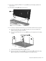
Disconnect the microphone cable, Open the computer as far as it will open.
 |
View all HP ProBook 6550b manuals
Add to My Manuals
Save this manual to your list of manuals |
Page 127 highlights
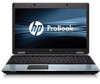
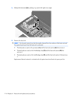
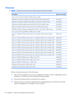
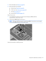
4. Remove the battery (see Battery on page 79). 5. Disconnect the antenna cables from the WLAN (see WLAN module on page 88) and WWAN modules (see WWAN module on page 92). 6. Remove the keyboard (see Keyboard on page 96). 7. Remove the switch cover (see Switch cover on page 103). Remove the display assembly: 1. Close the computer. 2. Position the computer with the rear panel toward you. 3. Remove the four slotted Torx T8M2.5×11.0 screws that secure the display assembly to the computer. 4. Turn the computer display-side up, with the front toward you. 5. Open the computer as far as it will open. 6. Disconnect the microphone cable (1) from the system board. 7. Remove the microphone cable from the clips and routing channel (2) built into the top cover. Component replacement procedures 119
-
 1
1 -
2
-
3
-
4
-
5
-
6
-
7
-
8
-
9
-
10
-
11
-
12
-
13
-
14
-
15
-
16
-
17
-
18
-
19
-
20
-
21
-
22
-
23
-
24
-
25
-
26
-
27
-
28
-
29
-
30
-
31
-
32
-
33
-
34
-
35
-
36
-
37
-
38
-
39
-
40
-
41
-
42
-
43
-
44
-
45
-
46
-
47
-
48
-
49
-
50
-
51
-
52
-
53
-
54
-
55
-
56
-
57
-
58
-
59
-
60
-
61
-
62
-
63
-
64
-
65
-
66
-
67
-
68
-
69
-
70
-
71
-
72
-
73
-
74
-
75
-
76
-
77
-
78
-
79
-
80
-
81
-
82
-
83
-
84
-
85
-
86
-
87
-
88
-
89
-
90
-
91
-
92
-
93
-
94
-
95
-
96
-
97
-
98
-
99
-
100
-
101
-
102
-
103
-
104
-
105
-
106
-
107
-
108
-
109
-
110
-
111
-
112
-
113
-
114
-
115
-
116
-
117
-
118
-
119
-
120
-
121
-
 122
122 -
 123
123 -
 124
124 -
 125
125 -
 126
126 -
 127
127 -
 128
128 -
 129
129 -
 130
130 -
 131
131 -
 132
132 -
133
-
134
-
135
-
136
-
137
-
138
-
139
-
140
-
141
-
142
-
143
-
144
-
145
-
146
-
147
-
148
-
149
-
150
-
151
-
152
-
153
-
154
-
155
-
156
-
157
-
158
-
159
-
160
-
161
-
162
-
163
-
164
-
165
-
166
-
167
-
168
-
169
-
170
-
171
-
172
-
173
-
174
-
175
-
176
-
177
-
178
-
179
-
180
-
181
-
182
-
183
-
184
-
185
-
186
-
187
-
188
-
189
-
190
-
191
-
192
-
193
-
194
-
195
-
196
-
197
-
198
-
199
-
200
-
201
-
202
-
203
-
204
-
205
-
206
-
207
-
208
-
209
-
210
-
211
-
212
-
213
-
214
-
215
-
216
-
217
-
218
-
219
 |
 |