HP ProBook 6550b HP ProBook 6455b, 6555b, 6450b,and 6550b Notebook PCs - Maint - Page 131
upside down in front of the display enclosure., and then swing it up and forward until it rests
 |
View all HP ProBook 6550b manuals
Add to My Manuals
Save this manual to your list of manuals |
Page 131 highlights
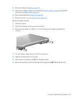
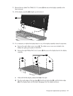
14. If it is necessary to replace the webcam module: a. Release the webcam module (1) as far from the display enclosure as the webcam module cable allows. (The webcam module is attached to the display enclosure with double-sided tape.) b. Disconnect the webcam module cable (2) from the webcam module. c. Remove the webcam module (3). The webcam module is available using spare part number 611026-001. 15. If it is necessary to replace the display panel cable or display hinges: a. Remove the two Phillips PM2.5×6.0 screws that secure the display panel to the display enclosure. b. Lift the top edge of the display panel (1), and then swing it up and forward until it rests upside down in front of the display enclosure. c. Release the support strip (2) and locking bar (3) that secure the display panel cable to the display panel. Component replacement procedures 123
-
 1
1 -
2
-
3
-
4
-
5
-
6
-
7
-
8
-
9
-
10
-
11
-
12
-
13
-
14
-
15
-
16
-
17
-
18
-
19
-
20
-
21
-
22
-
23
-
24
-
25
-
26
-
27
-
28
-
29
-
30
-
31
-
32
-
33
-
34
-
35
-
36
-
37
-
38
-
39
-
40
-
41
-
42
-
43
-
44
-
45
-
46
-
47
-
48
-
49
-
50
-
51
-
52
-
53
-
54
-
55
-
56
-
57
-
58
-
59
-
60
-
61
-
62
-
63
-
64
-
65
-
66
-
67
-
68
-
69
-
70
-
71
-
72
-
73
-
74
-
75
-
76
-
77
-
78
-
79
-
80
-
81
-
82
-
83
-
84
-
85
-
86
-
87
-
88
-
89
-
90
-
91
-
92
-
93
-
94
-
95
-
96
-
97
-
98
-
99
-
100
-
101
-
102
-
103
-
104
-
105
-
106
-
107
-
108
-
109
-
110
-
111
-
112
-
113
-
114
-
115
-
116
-
117
-
118
-
119
-
120
-
121
-
122
-
123
-
124
-
125
-
 126
126 -
 127
127 -
 128
128 -
 129
129 -
 130
130 -
 131
131 -
 132
132 -
 133
133 -
 134
134 -
 135
135 -
 136
136 -
137
-
138
-
139
-
140
-
141
-
142
-
143
-
144
-
145
-
146
-
147
-
148
-
149
-
150
-
151
-
152
-
153
-
154
-
155
-
156
-
157
-
158
-
159
-
160
-
161
-
162
-
163
-
164
-
165
-
166
-
167
-
168
-
169
-
170
-
171
-
172
-
173
-
174
-
175
-
176
-
177
-
178
-
179
-
180
-
181
-
182
-
183
-
184
-
185
-
186
-
187
-
188
-
189
-
190
-
191
-
192
-
193
-
194
-
195
-
196
-
197
-
198
-
199
-
200
-
201
-
202
-
203
-
204
-
205
-
206
-
207
-
208
-
209
-
210
-
211
-
212
-
213
-
214
-
215
-
216
-
217
-
218
-
219
 |
 |
