HP ProBook 6550b HP ProBook 6455b, 6555b, 6450b,and 6550b Notebook PCs - Maint - Page 125
straight up and remove it., Lift the processor
 |
View all HP ProBook 6550b manuals
Add to My Manuals
Save this manual to your list of manuals |
Page 125 highlights
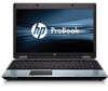
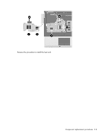
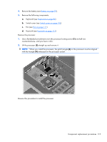
4. Remove the battery (see Battery on page 79). 5. Remove the following components: a. Keyboard (see Keyboard on page 96) b. Switch cover (see Switch cover on page 103) c. Fan (see Fan on page 111) d. Heat sink (see Heat sink on page 113) Remove the processor: 1. Use a flat-bladed screwdriver to turn the processor locking screw (1) one-half turn counterclockwise, until you hear a click. 2. Lift the processor (2) straight up and remove it. NOTE: When you install the processor, the gold triangle (3) on the processor must be aligned with the triangle (4) embossed on the processor socket. Reverse this procedure to install the processor. Component replacement procedures 117
-
 1
1 -
2
-
3
-
4
-
5
-
6
-
7
-
8
-
9
-
10
-
11
-
12
-
13
-
14
-
15
-
16
-
17
-
18
-
19
-
20
-
21
-
22
-
23
-
24
-
25
-
26
-
27
-
28
-
29
-
30
-
31
-
32
-
33
-
34
-
35
-
36
-
37
-
38
-
39
-
40
-
41
-
42
-
43
-
44
-
45
-
46
-
47
-
48
-
49
-
50
-
51
-
52
-
53
-
54
-
55
-
56
-
57
-
58
-
59
-
60
-
61
-
62
-
63
-
64
-
65
-
66
-
67
-
68
-
69
-
70
-
71
-
72
-
73
-
74
-
75
-
76
-
77
-
78
-
79
-
80
-
81
-
82
-
83
-
84
-
85
-
86
-
87
-
88
-
89
-
90
-
91
-
92
-
93
-
94
-
95
-
96
-
97
-
98
-
99
-
100
-
101
-
102
-
103
-
104
-
105
-
106
-
107
-
108
-
109
-
110
-
111
-
112
-
113
-
114
-
115
-
116
-
117
-
118
-
119
-
 120
120 -
 121
121 -
 122
122 -
 123
123 -
 124
124 -
 125
125 -
 126
126 -
 127
127 -
 128
128 -
 129
129 -
 130
130 -
131
-
132
-
133
-
134
-
135
-
136
-
137
-
138
-
139
-
140
-
141
-
142
-
143
-
144
-
145
-
146
-
147
-
148
-
149
-
150
-
151
-
152
-
153
-
154
-
155
-
156
-
157
-
158
-
159
-
160
-
161
-
162
-
163
-
164
-
165
-
166
-
167
-
168
-
169
-
170
-
171
-
172
-
173
-
174
-
175
-
176
-
177
-
178
-
179
-
180
-
181
-
182
-
183
-
184
-
185
-
186
-
187
-
188
-
189
-
190
-
191
-
192
-
193
-
194
-
195
-
196
-
197
-
198
-
199
-
200
-
201
-
202
-
203
-
204
-
205
-
206
-
207
-
208
-
209
-
210
-
211
-
212
-
213
-
214
-
215
-
216
-
217
-
218
-
219
 |
 |
4.
Remove the battery (see
Battery
on page
79
).
5.
Remove the following components:
a.
Keyboard (see
Keyboard
on page
96
)
b.
Switch cover (see
Switch cover
on page
103
)
c.
Fan (see
Fan
on page
111
)
d.
Heat sink (see
Heat sink
on page
113
)
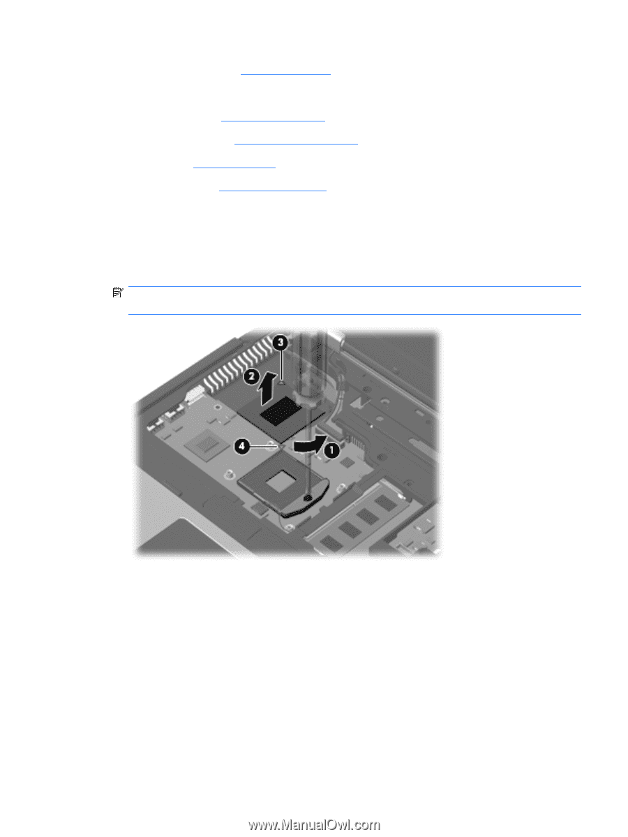
Remove the processor:
1.
Use a flat-bladed screwdriver to turn the processor locking screw
(1)
one-half turn
counterclockwise, until you hear a click.
2.
Lift the processor
(2)
straight up and remove it.
NOTE:
When you install the processor, the gold triangle
(3)
on the processor must be aligned
with the triangle
(4)
embossed on the processor socket.
Reverse this procedure to install the processor.
Component replacement procedures
117