HP ProLiant 2500 Compaq ProLiant 2500 Servers Installation Guide - Page 71
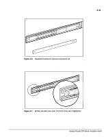
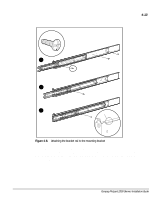
Adjust the inner slide to access the other two screw holes, one at a time
 |
View all HP ProLiant 2500 manuals
Add to My Manuals
Save this manual to your list of manuals |
Page 71 highlights
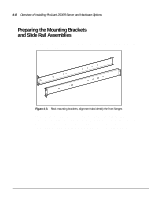
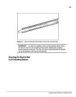
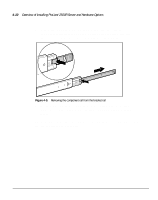
4-12 Overview of Installing ProLiant 2500R Server and Hardware Options 4. Lay the bracket rail inside the mounting bracket with the front of both pieces oriented in the same direction. Align the front screw holes in the mounting bracket and the bracket rail. To identify the front of the mounting bracket and the bracket rail: The front of the mounting bracket has alignment tabs on its flange. The front of the bracket rail allows the inner slide to move forward on ball bearings. 5. Extend the inner slide from the front of the bracket rail. With this piece extended, you will see two screw holes aligned in the mounting bracket and the bracket rail. These are the two exposed holes near the back end of the bracket rail and the front hole accessible through a slot in the inner slide. 6. Fasten the bracket rail to the mounting bracket with two 8-32 x 1/4-inch slotted screws. (Do not use nuts or washers with the screws.) See step of the following figure. 7. Adjust the inner slide to access the other two screw holes, one at a time, through the slotted opening in the inner slide. Use two more 8-32 x 1/4inch slotted screws to fasten the bracket rail to the mounting bracket. See steps and of the following figure. The following figure shows inserting the screws into the appropriate holes. The screws will line up with the 22-inch markings stamped along one edge of the mounting bracket. These marks identify the mounting holes for the 22-inch slides used in Compaq racks. (The 24-inch markings stamped along the other edge are for use with the 24-inch slides that support other components.)
-
 1
1 -
2
-
3
-
4
-
5
-
6
-
7
-
8
-
9
-
10
-
11
-
12
-
13
-
14
-
15
-
16
-
17
-
18
-
19
-
20
-
21
-
22
-
23
-
24
-
25
-
26
-
27
-
28
-
29
-
30
-
31
-
32
-
33
-
34
-
35
-
36
-
37
-
38
-
39
-
40
-
41
-
42
-
43
-
44
-
45
-
46
-
47
-
48
-
49
-
50
-
51
-
52
-
53
-
54
-
55
-
56
-
57
-
58
-
59
-
60
-
61
-
62
-
63
-
64
-
65
-
 66
66 -
 67
67 -
 68
68 -
 69
69 -
 70
70 -
 71
71 -
 72
72 -
 73
73 -
 74
74 -
 75
75 -
 76
76 -
77
-
78
-
79
-
80
-
81
-
82
-
83
-
84
-
85
-
86
-
87
-
88
-
89
-
90
-
91
-
92
-
93
-
94
-
95
-
96
-
97
-
98
-
99
-
100
-
101
-
102
-
103
-
104
-
105
-
106
-
107
-
108
-
109
-
110
-
111
 |
 |
