HP Xw4300 HP xw Workstation series Setup and Troubleshooting Guide - Page 16
Front panel components, - specifications
 |
UPC - 882780170056
View all HP Xw4300 manuals
Add to My Manuals
Save this manual to your list of manuals |
Page 16 highlights
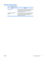
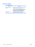
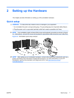
Front panel components Figure 2-3 is for reference only, and shows examples of different workstation series. Your HP workstation might look different. Figure 2-3 Workstation series front panel examples xw4000 Series xw6000 Series xw8000/xw9000 Series Table 2-1 Front panel component examples* Item Symbol Description 1 Optical drive Item 6 Symbol Description Headphone connector 2 5.25-inch drive bay 7 USB 2.0 (Universal Serial Bus) ports 3 Diskette drive (optional) 8 Hard drive activity light 4 IEEE-1394a connector 9 Power button 5 Microphone connector 10 Power on light * Refer to the Service and Technical Reference Guide for your workstation for specific front panel component information. 10 Chapter 2 Setting up the Hardware ENWW
-
 1
1 -
2
-
3
-
4
-
5
-
6
-
7
-
8
-
9
-
10
-
 11
11 -
 12
12 -
 13
13 -
 14
14 -
 15
15 -
 16
16 -
 17
17 -
 18
18 -
 19
19 -
 20
20 -
 21
21 -
22
-
23
-
24
-
25
-
26
-
27
-
28
-
29
-
30
-
31
-
32
-
33
-
34
-
35
-
36
-
37
-
38
-
39
-
40
-
41
-
42
-
43
-
44
-
45
-
46
-
47
-
48
-
49
-
50
-
51
-
52
 |
 |

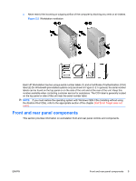
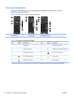
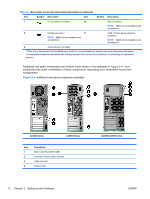
Front panel components
Figure 2–3 is for reference only, and shows examples of different workstation series. Your HP
workstation might look different.
Figure 2-3
Workstation series front panel examples
xw4000 Series
xw6000 Series
xw8000/xw9000 Series
Table 2-1
Front panel component examples
*
Item
Symbol
Description
Item
Symbol
Description
1
Optical drive
6
Headphone connector
2
5.25-inch drive bay
7
USB 2.0 (Universal Serial Bus) ports
3
Diskette drive (optional)
8
Hard drive activity light
4
IEEE-1394a connector
9
Power button
5
Microphone connector
10
Power on light
*
Refer to the
Service and Technical Reference Guide
for your workstation for specific front panel component information.
10
Chapter 2
Setting up the Hardware
ENWW