HP Xw4300 HP xw Workstation series Setup and Troubleshooting Guide - Page 18
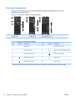
workstation has some combination of these components, depending upon workstation model - workstation specifications
 |
UPC - 882780170056
View all HP Xw4300 manuals
Add to My Manuals
Save this manual to your list of manuals |
Page 18 highlights
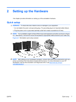
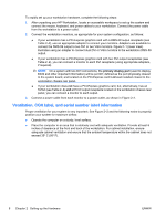
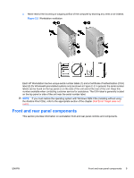
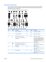
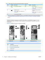
Table 2-2 Rear panel connector and control description (continued) Item Symbol Description Item Symbol Description 7 RJ-45 network connector 16 SAS Connector NOTE: Might not be available on all workstations. 8 Parallel connector * 17 DMS-59 high density graphics NOTE: Might not be available on all connector workstations. NOTE: Might not be available on all workstations. 9 SVGA Monitor Connector * Refer to the Service and Technical Reference Guide for your workstation for specific rear panel component information. The rear panel connectors are labeled with industry-standard icons and colors to assist you in connecting your peripheral devices. Additional rear panel components can include those shown in the examples in Figure 2-5. Your workstation has some combination of these components, depending upon workstation model and configuration. Figure 2-5 Additional rear panel component examples xw4000 Series xw6000 Series Item 1 2 3 4 Description Built-in Self Test (BIST) LED Universal chassis clamp opening Cable lock slot Padlock loop xw8000/xw9000 Series 12 Chapter 2 Setting up the Hardware ENWW
-
 1
1 -
2
-
3
-
4
-
5
-
6
-
7
-
8
-
9
-
10
-
11
-
12
-
 13
13 -
 14
14 -
 15
15 -
 16
16 -
 17
17 -
 18
18 -
 19
19 -
 20
20 -
 21
21 -
 22
22 -
 23
23 -
24
-
25
-
26
-
27
-
28
-
29
-
30
-
31
-
32
-
33
-
34
-
35
-
36
-
37
-
38
-
39
-
40
-
41
-
42
-
43
-
44
-
45
-
46
-
47
-
48
-
49
-
50
-
51
-
52
 |
 |
