HP Z600 HP Z Workstation series User Guide - Page 48
Preparing for component installation, Disassembly and installation preparation, Preparing
 |
UPC - 884962074053
View all HP Z600 manuals
Add to My Manuals
Save this manual to your list of manuals |
Page 48 highlights
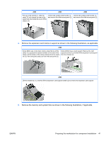
6 Preparing for component installation To facilitate the installation of components, several steps can be taken to prepare the workstation. This section describes how to prepare your workstation for component installation. Disassembly and installation preparation Use the following table to determine the order of workstation disassembly required before installing components. (Your workstation components may be different than those listed.) Table 6-1 Workstation component installation To install... Remove... Then remove... Then remove... Then remove... Then remove... Memory Chassis locks* Side access panel Air flow guide (Z800, and optional on Z400) Memory fan or airflow guide (if required) Expansion card Chassis locks (PCI/PCIe) Side access panel Air flow guide (Z800) Expansion card Expansion card support slot cover Hard drive Chassis locks Side access panel Optical drive Chassis locks Side access panel Front bezel (Z400 only) Air flow guide Expansion card (Z800 and support (Z800) optional on Z400) * See the workstation Maintenance and Service Guide for chassis lock locations and operation instructions. Preparing the workstation for component installation To prepare the workstation: NOTE: The workstation contains green, plastic touch points at locations where you must manipulate a button or lever. Green touch points on some components indicate tool-less removal of those components. 1. Disconnect power from the system. 2. Unlock the side access panel or remove any chassis locks. 3. Remove the side access panel as shown in the following illustrations. 40 Chapter 6 Preparing for component installation ENWW
-
 1
1 -
2
-
3
-
4
-
5
-
6
-
7
-
8
-
9
-
10
-
11
-
12
-
13
-
14
-
15
-
16
-
17
-
18
-
19
-
20
-
21
-
22
-
23
-
24
-
25
-
26
-
27
-
28
-
29
-
30
-
31
-
32
-
33
-
34
-
35
-
36
-
37
-
38
-
39
-
40
-
41
-
42
-
 43
43 -
 44
44 -
 45
45 -
 46
46 -
 47
47 -
 48
48 -
 49
49 -
 50
50 -
 51
51 -
 52
52 -
 53
53 -
54
-
55
-
56
-
57
-
58
-
59
-
60
-
61
-
62
-
63
-
64
-
65
-
66
-
67
-
68
-
69
-
70
-
71
-
72
 |
 |