HP Z600 HP Z Workstation series User Guide - Page 56
Ensure that the airflow guide secures even with the end of the FDD bay
 |
UPC - 884962074053
View all HP Z600 manuals
Add to My Manuals
Save this manual to your list of manuals |
Page 56 highlights
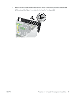
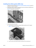
4. Route the CPU power cable (P3) through the opening next to the power supply as shown in the following figure. Figure 7-5 Routing the CPU power cable 5. Secure the airflow guide in the chassis. a. Insert the tab on the airflow guide into the slot next to the yellow ODD release lever (1), and then press down as shown in the following figure. Figure 7-6 Securing the airflow guide b. Ensure that the airflow guide secures even with the end of the FDD bay, and that the latch (2) engages with the slot in the internal bay cover. 48 Chapter 7 Installing memory ENWW
-
 1
1 -
2
-
3
-
4
-
5
-
6
-
7
-
8
-
9
-
10
-
11
-
12
-
13
-
14
-
15
-
16
-
17
-
18
-
19
-
20
-
21
-
22
-
23
-
24
-
25
-
26
-
27
-
28
-
29
-
30
-
31
-
32
-
33
-
34
-
35
-
36
-
37
-
38
-
39
-
40
-
41
-
42
-
43
-
44
-
45
-
46
-
47
-
48
-
49
-
50
-
 51
51 -
 52
52 -
 53
53 -
 54
54 -
 55
55 -
 56
56 -
 57
57 -
 58
58 -
 59
59 -
 60
60 -
 61
61 -
62
-
63
-
64
-
65
-
66
-
67
-
68
-
69
-
70
-
71
-
72
 |
 |
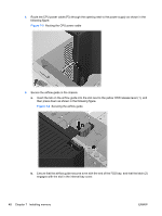
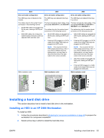
4.
Route the CPU power cable (P3) through the opening next to the power supply as shown in the
following figure.
Figure 7-5
Routing the CPU power cable
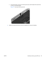
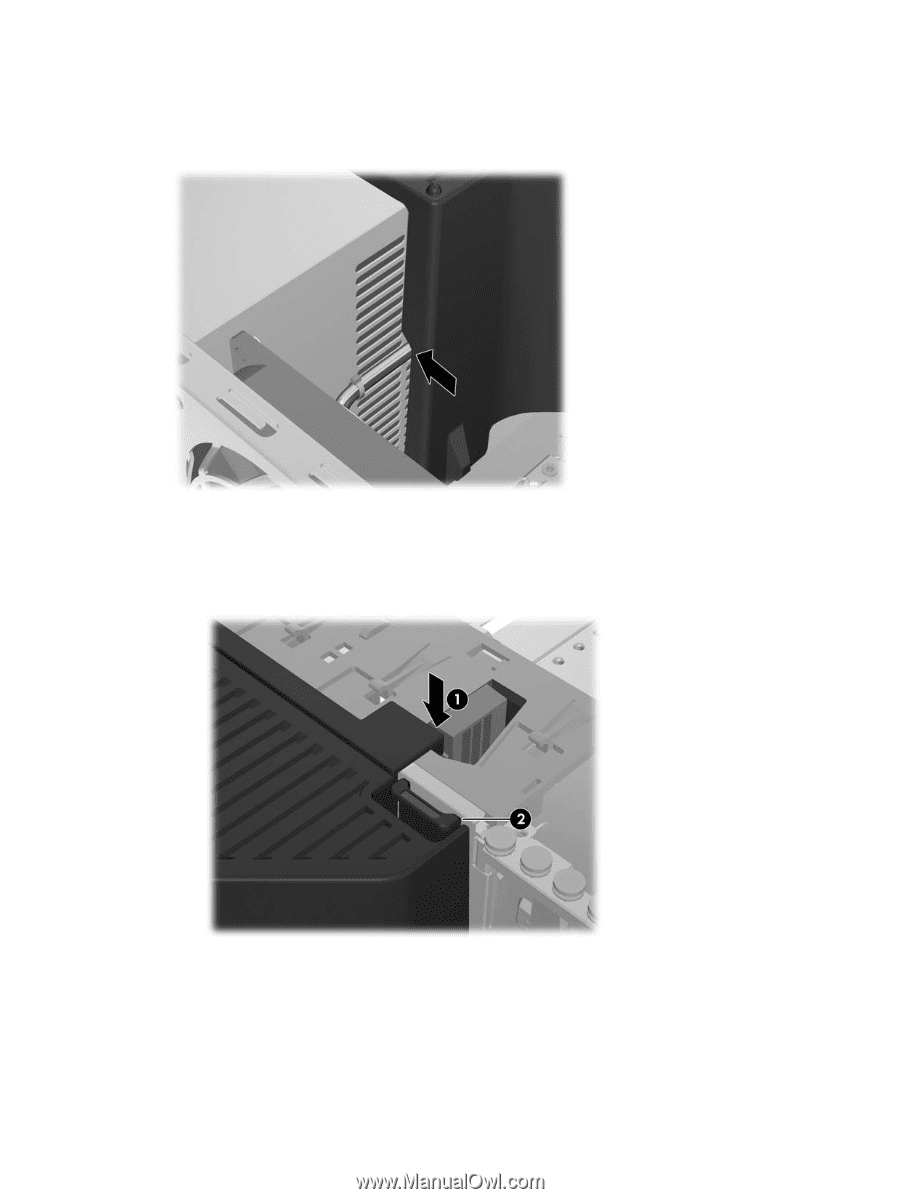
5.
Secure the airflow guide in the chassis.
a.
Insert the tab on the airflow guide into the slot next to the yellow ODD release lever (1), and
then press down as shown in the following figure.
Figure 7-6
Securing the airflow guide
b.
Ensure that the airflow guide secures even with the end of the FDD bay, and that the latch (2)
engages with the slot in the internal bay cover.
48
Chapter 7
Installing memory
ENWW