HP Z600 HP Z Workstation series User Guide - Page 55
Installing the airflow guide (Z400 only), Set the airflow guide into the chassis.
 |
UPC - 884962074053
View all HP Z600 manuals
Add to My Manuals
Save this manual to your list of manuals |
Page 55 highlights
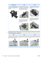
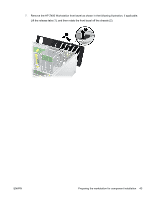
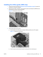
Installing the airflow guide (Z400 only) 1. Follow the procedures described in Preparing for component installation on page 40 to prepare the workstation for component installation. 2. Press the power cables, including P1, down toward the system board between the DIMM slots and the internal bay, as shown in the following figure. Figure 7-3 Positioning the chassis cables 3. Set the airflow guide into the chassis. a. Place the edge of the airflow guide (1) between DIMM socket #6 and the CPU heatsink. Figure 7-4 Installing the airflow guide b. Route the power and data cables through the opening next to the internal bay (2). ENWW Installing the airflow guide (Z400 only) 47
-
 1
1 -
2
-
3
-
4
-
5
-
6
-
7
-
8
-
9
-
10
-
11
-
12
-
13
-
14
-
15
-
16
-
17
-
18
-
19
-
20
-
21
-
22
-
23
-
24
-
25
-
26
-
27
-
28
-
29
-
30
-
31
-
32
-
33
-
34
-
35
-
36
-
37
-
38
-
39
-
40
-
41
-
42
-
43
-
44
-
45
-
46
-
47
-
48
-
49
-
 50
50 -
 51
51 -
 52
52 -
 53
53 -
 54
54 -
 55
55 -
 56
56 -
 57
57 -
 58
58 -
 59
59 -
 60
60 -
61
-
62
-
63
-
64
-
65
-
66
-
67
-
68
-
69
-
70
-
71
-
72
 |
 |
Installing the airflow guide (Z400 only)
1.
Follow the procedures described in
Preparing for component installation
on page
40
to prepare the
workstation for component installation.
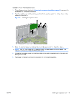
2.
Press the power cables, including P1, down toward the system board between the DIMM slots and
the internal bay, as shown in the following figure.
Figure 7-3
Positioning the chassis cables
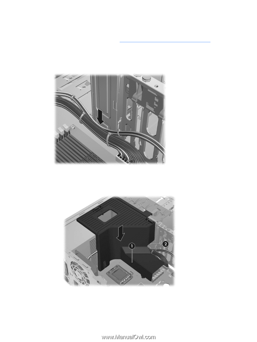
3.
Set the airflow guide into the chassis.
a.
Place the edge of the airflow guide (1) between DIMM socket #6 and the CPU heatsink.
Figure 7-4
Installing the airflow guide
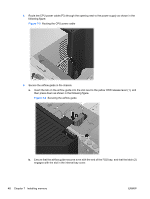
b.
Route the power and data cables through the opening next to the internal bay (2).
ENWW
Installing the airflow guide (Z400 only)
47