HP Z600 HP Z Workstation series User Guide - Page 50
the following illustrations, if applicable.
 |
UPC - 884962074053
View all HP Z600 manuals
Add to My Manuals
Save this manual to your list of manuals |
Page 50 highlights
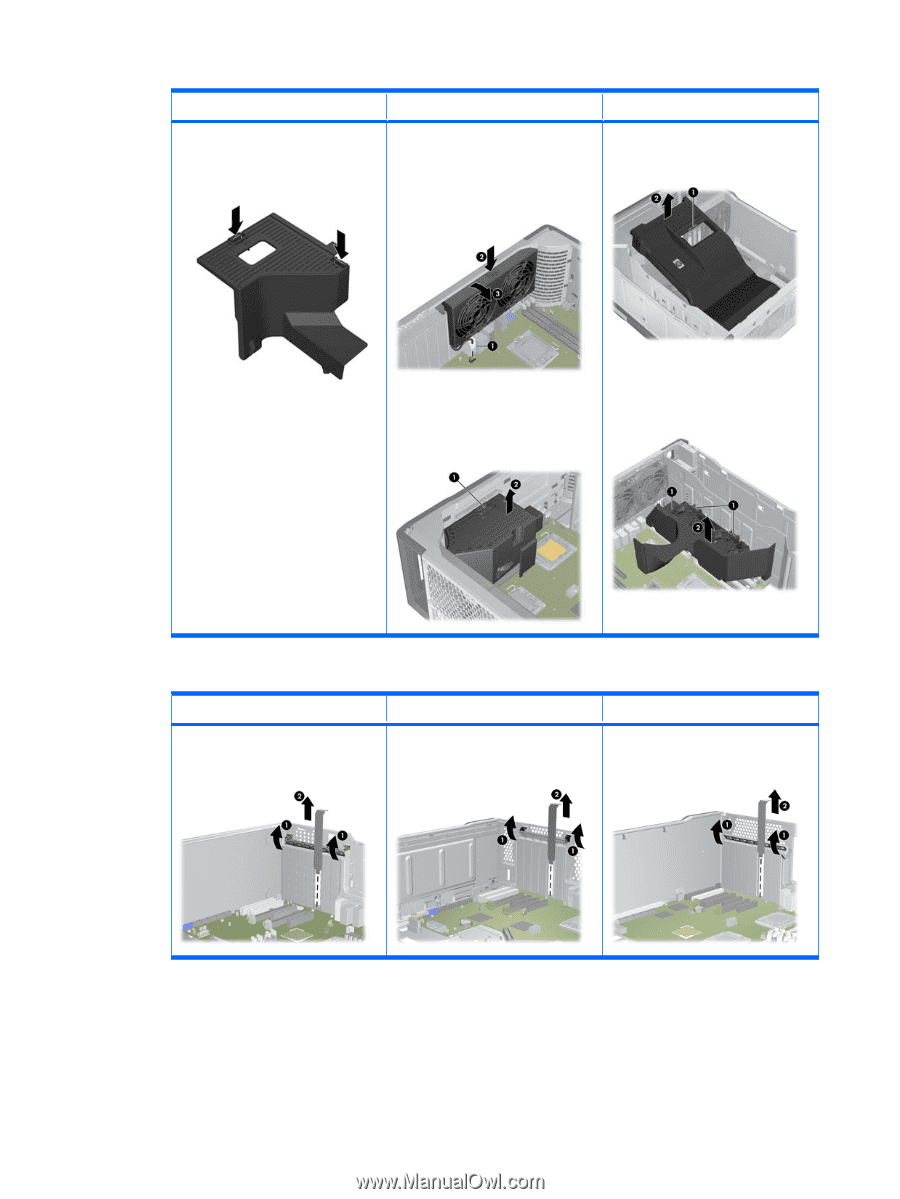
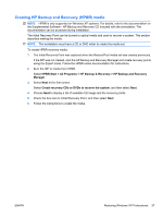
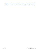
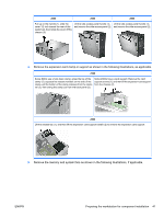
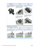
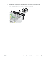
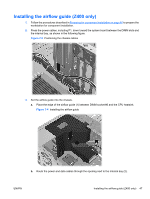
Z400 (optional) Z600 Press the airflow guide release latches as shown in the following figure, and guide the airflow guide out of the chassis. Disconnect the fan cable from the system board (1), press the release tab at the green touch point (2), and then rotate the rear system fan assembly from the chassis (3). Z800 Remove the Z800 air flow guide as shown in the following illustration, if applicable. Press the release tab at the green touch point (1), and then lift the memory fan assembly from the chassis (2). Press the release tabs at the green touch points (1), and then lift the memory fan assembly from the chassis (2). 6. Raise the expansion card retention clamp and remove the expansion card slot cover as shown in the following illustrations, if applicable. Z400 Z600 Z800 Open the card retention clamp at the Open the card retention clamp (1), and Open the card retention clamp (1), and green touch points (1), and then lift the then lift the slot cover from the chassis then lift the slot cover from the chassis slot cover from the chassis (2). (2). (2). 42 Chapter 6 Preparing for component installation ENWW
-
 1
1 -
2
-
3
-
4
-
5
-
6
-
7
-
8
-
9
-
10
-
11
-
12
-
13
-
14
-
15
-
16
-
17
-
18
-
19
-
20
-
21
-
22
-
23
-
24
-
25
-
26
-
27
-
28
-
29
-
30
-
31
-
32
-
33
-
34
-
35
-
36
-
37
-
38
-
39
-
40
-
41
-
42
-
43
-
44
-
 45
45 -
 46
46 -
 47
47 -
 48
48 -
 49
49 -
 50
50 -
 51
51 -
 52
52 -
 53
53 -
 54
54 -
 55
55 -
56
-
57
-
58
-
59
-
60
-
61
-
62
-
63
-
64
-
65
-
66
-
67
-
68
-
69
-
70
-
71
-
72
 |
 |