IBM 2498-B40 User Guide - Page 29
Port side of the switch, supportSave - firmware
 |
View all IBM 2498-B40 manuals
Add to My Manuals
Save this manual to your list of manuals |
Page 29 highlights
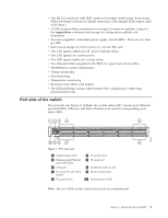
v One RS-232 serial port with RJ45 connector for initial switch setup (if not using EZSwitch Setup) and factory default restoration. (The integral LEDs remain unlit at all times.) v A USB port providing connections for storage for firmware updates, output of the supportSave command and storage for configuration uploads and downloads v Two hot-swappable, redundant power supply and fan FRUs. There are two fans per FRU v Rack-mount design (1U form factor) in a 19-inch EIA rack v One LED (green/amber) per FC port to indicate status v One LED (green) for system power v One LED (green/amber) for system status v Two Ethernet LEDs (integrated with RJ45) for speed and activity status v SEEPROM for switch identification v Voltage monitoring v Fan monitoring v Temperature monitoring v Real-time clock (RTC) with battery v The EZSwitchSetup wizard, which makes SAN configuration a three-step point-and-click task Port side of the switch The port side (see Figure 1) includes the system status LED, console port, Ethernet port and LEDs, USB port, and Fibre Channel ports and the corresponding port status LEDs. 123 4 5 b48f006 10 9 8 7 6 Figure 1. Port side view 1 System status LED 2 Management Ethernet port with LEDs 3 USB port 4 FC ports 0-3 (all LEDs above) 5 FC ports 40-43 6 FC ports 44-47 7 FC ports 4-7 8 Switch ID pull-out tab 9 Serial console port 10 System power LED Note: The two LEDs on the serial console port are nonfunctional. Chapter 1. Introducing the SAN48B-5 3
-
 1
1 -
2
-
3
-
4
-
5
-
6
-
7
-
8
-
9
-
10
-
11
-
12
-
13
-
14
-
15
-
16
-
17
-
18
-
19
-
20
-
21
-
22
-
23
-
 24
24 -
 25
25 -
 26
26 -
 27
27 -
 28
28 -
 29
29 -
 30
30 -
 31
31 -
 32
32 -
 33
33 -
 34
34 -
35
-
36
-
37
-
38
-
39
-
40
-
41
-
42
-
43
-
44
-
45
-
46
-
47
-
48
-
49
-
50
-
51
-
52
-
53
-
54
-
55
-
56
-
57
-
58
-
59
-
60
-
61
-
62
-
63
-
64
-
65
-
66
-
67
-
68
-
69
-
70
-
71
-
72
-
73
-
74
-
75
-
76
-
77
-
78
 |
 |
