IBM 2498-B40 User Guide - Page 49
Using and maintaining the switch, Powering the switch on and off, Interpreting LEDs
 |
View all IBM 2498-B40 manuals
Add to My Manuals
Save this manual to your list of manuals |
Page 49 highlights
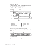
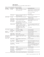
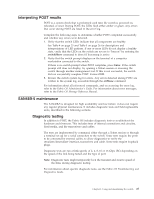
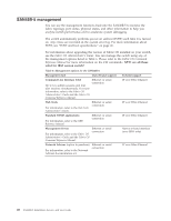
Chapter 3. Using and maintaining the switch This chapter provides information about operating and maintaining the switch and includes these topics. v "Powering the switch on and off" v "Interpreting LEDs" v "POST and boot specifications" on page 26 v "Interpreting POST results" on page 27 v "SAN48B-5 maintenance" on page 27 v "SAN48B-5 management" on page 28 Powering the switch on and off Complete the following steps to power the switch on. 1. Connect both power cords to the power connectors on the power supplies and to separate power sources. 2. Set the AC power switches to "|". Power is supplied to the switch as soon as the first power supply is connected and powered on. The switch runs POST by default each time it is powered on; it can take several minutes to boot and complete POST. . To power the switch off, power off both power supplies by setting each AC power switch to "O". All devices are returned to their initial state the next time the switch is powered on. Attention: Power is still supplied to the switch if either of the two power cords are connected. To fully remove power from the switch, both power cords must be disconnected. Interpreting LEDs System activity and status can be determined through the activity of the LEDs on the switch. There are three possible LED states: no light, a steady light, and a flashing light. Flashing lights may be slow, fast, or flickering. The lights are green or amber. Sometimes, the LEDs flash either of the colors during boot, POST, or other diagnostic tests. This is normal; it does not indicate a problem unless the LEDs do not indicate a healthy state after all boot processes and diagnostic tests are complete. LED locations The port side of the switch has the following LEDs (see Figure 11 on page 24). v One system status LED (above) on the left side v One power LED (below) on the left side v Two Ethernet Port LEDs (both green) © Copyright IBM Corp. 2011 23
-
 1
1 -
2
-
3
-
4
-
5
-
6
-
7
-
8
-
9
-
10
-
11
-
12
-
13
-
14
-
15
-
16
-
17
-
18
-
19
-
20
-
21
-
22
-
23
-
24
-
25
-
26
-
27
-
28
-
29
-
30
-
31
-
32
-
33
-
34
-
35
-
36
-
37
-
38
-
39
-
40
-
41
-
42
-
43
-
 44
44 -
 45
45 -
 46
46 -
 47
47 -
 48
48 -
 49
49 -
 50
50 -
 51
51 -
 52
52 -
 53
53 -
 54
54 -
55
-
56
-
57
-
58
-
59
-
60
-
61
-
62
-
63
-
64
-
65
-
66
-
67
-
68
-
69
-
70
-
71
-
72
-
73
-
74
-
75
-
76
-
77
-
78
 |
 |
