IBM 2498-B40 User Guide - Page 32
Site preparation and installation requirements, Electrical requirements, Environmental requirements
 |
View all IBM 2498-B40 manuals
Add to My Manuals
Save this manual to your list of manuals |
Page 32 highlights
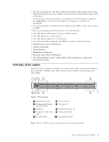
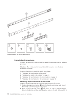
Attention: Retain this paperpack in a safe place. The transaction keys in the paperpack are required for activation of optional features on the switch. Once a feature is activated, its activation key is associated with a specific product WWN and serial number. Site preparation and installation requirements The following conditions are required to ensure correct installation and operation. Electrical requirements For successful installation and operation of the switch, ensure that the following electrical requirements are met: v The primary outlet is correctly wired, protected by a circuit breaker, and grounded in accordance with local electrical codes. v The supply circuit, line fusing, and wire size are adequate, as specified by the electrical rating on the switch nameplate. v The power supply standards are met. See "Power supply specifications" on page 36. Attention: To maximize fault tolerance, connect each power cord to a separate power source. Environmental requirements For successful installation and operation of the switch, ensure that the following environmental requirements are met: v At a minimum, adequate cooling requires that you install the switch with the intake side facing the cool-air aisle. v All equipment in the rack should force air in the same direction to avoid intake of exhaust air. v A maximum of 102 cubic meters/hour (60 cubic feet/minute) and a minimum of 74..8 cubic meters/hour (44 cubic feet/minute) of air flow is available to the air intake. v The ambient air temperature does not exceed 40° C (104° F) while the switch is operating. Cabinet requirements For successful installation and operation of the switch in a cabinet, ensure that the following cabinet requirements are met: v The cabinet must be a standard EIA cabinet. v A cabinet space that is one rack unit (1U) high; 4.45 cm (1.75 inches) high and 48.3 cm (19 inches) wide. v The rack kit option for the switch uses rails that are slimmer than standard rails to accommodate the slightly wider chassis. Be sure to use one of these kits. Do not use standard rails to install the switch in a rack, they will not fit with the switch. v The equipment in the cabinet is grounded through a reliable branch circuit connection and maintain ground at all times. Do not rely on a secondary connection to a branch circuit, such as a power strip. v Airflow and temperature requirements are met on an ongoing basis, particularly if the switch is installed in a closed or multicabinet assembly. v The additional weight of the switch does not exceed the cabinet's weight limits or unbalance the cabinet in any way. 6 SAN48B-5 Installation, Service, and User Guide
-
 1
1 -
2
-
3
-
4
-
5
-
6
-
7
-
8
-
9
-
10
-
11
-
12
-
13
-
14
-
15
-
16
-
17
-
18
-
19
-
20
-
21
-
22
-
23
-
24
-
25
-
26
-
 27
27 -
 28
28 -
 29
29 -
 30
30 -
 31
31 -
 32
32 -
 33
33 -
 34
34 -
 35
35 -
 36
36 -
 37
37 -
38
-
39
-
40
-
41
-
42
-
43
-
44
-
45
-
46
-
47
-
48
-
49
-
50
-
51
-
52
-
53
-
54
-
55
-
56
-
57
-
58
-
59
-
60
-
61
-
62
-
63
-
64
-
65
-
66
-
67
-
68
-
69
-
70
-
71
-
72
-
73
-
74
-
75
-
76
-
77
-
78
 |
 |