IBM 2498-B40 User Guide - Page 50
shows the LEDs on port side of the switch.
 |
View all IBM 2498-B40 manuals
Add to My Manuals
Save this manual to your list of manuals |
Page 50 highlights
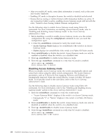
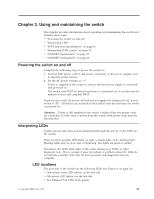
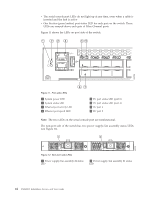
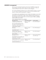
v The serial console port LEDs do not light up at any time, even when a cable is inserted and the link is active v One bicolor (green/amber) port status LED for each port on the switch. These LEDs are arrayed above each pair of Fibre Channel ports. Figure 11 shows the LEDs on port side of the switch. 1 23 4 56 b48f008 Figure 11. Port side LEDs 1 System power LED 2 System status LED 3 Ethernet port activity LED 4 Ethernet port speed LED 87 5 FC port status LED (port 0) 6 FC port status LED (port 4) 7 FC port 4 8 FC port 0 Note: The two LEDs on the serial console port are nonfunctional. The non-port side of the switch has two power supply/fan assembly status LEDs (see Figure 12). 1 2 Figure 12. Non-port side LEDs 1 Power supply/fan assembly #2 status LED 2 Power supply/fan assembly #1 status LED 24 SAN48B-5 Installation, Service, and User Guide b48f009
-
 1
1 -
2
-
3
-
4
-
5
-
6
-
7
-
8
-
9
-
10
-
11
-
12
-
13
-
14
-
15
-
16
-
17
-
18
-
19
-
20
-
21
-
22
-
23
-
24
-
25
-
26
-
27
-
28
-
29
-
30
-
31
-
32
-
33
-
34
-
35
-
36
-
37
-
38
-
39
-
40
-
41
-
42
-
43
-
44
-
 45
45 -
 46
46 -
 47
47 -
 48
48 -
 49
49 -
 50
50 -
 51
51 -
 52
52 -
 53
53 -
 54
54 -
 55
55 -
56
-
57
-
58
-
59
-
60
-
61
-
62
-
63
-
64
-
65
-
66
-
67
-
68
-
69
-
70
-
71
-
72
-
73
-
74
-
75
-
76
-
77
-
78
 |
 |
