IBM 2498-B40 User Guide - Page 57
Determining the need to replace a power supply and fan assembly, Time required
 |
View all IBM 2498-B40 manuals
Add to My Manuals
Save this manual to your list of manuals |
Page 57 highlights
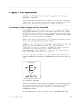
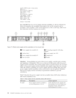
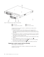
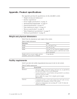
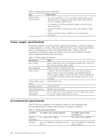
Table 7. Power supply and fan assembly status LED behavior (continued) LED color Description Action required Steady green Power supply and fan assembly is No action is required. operating normally. Flashing green (for more than 5 seconds) Power supply and fan assembly is faulty for one of the following reasons: v The assembly is switched off flashing for ~ 5 seconds, then off v The power cable is disconnected flashing for ~ 5 seconds, then off v The power supply and fan assembly has failed Check the power cable connection. Verify that the assembly is powered on Replace the power supply and fan assembly FRU. Note: When the switch is first powered on, the power supply and fan assembly status LED will show flashing until POST has completed Determining the need to replace a power supply and fan assembly Use one of the following methods to determine the status of the power supplies: v Check the power supply and fan assembly status LED next to the On/Off switch (see Figure 12 on page 24) v In Web Tools, click the Power Status icon. v Enter the psShow command at the prompt to display power supply and fan assembly status as shown below: br6510:admin> psshow Power Supply #1 is OK V10529, TQ2H0000030 ,60-0300031-01,X2, ,SP640 ,2X,TQ2H0000 Power Supply #2 is OK V10541, TQ2H0000189 ,60-0300031-01,X3, ,SP640-2P ,A ,TQ2H0000 br6510:admin> Time required Replacing a power supply and fan assembly in the switch should require less than two minutes to complete. Items required The following items are required to replace a power supply and fan assembly: v New power supply and fan assembly (must have the same airflow as the FRU being replaced) v Phillips-head screwdriver #1 Removing a power supply and fan assembly Refer to Figure 15 on page 32 for this procedure. Chapter 4. FRU replacement 31
-
 1
1 -
2
-
3
-
4
-
5
-
6
-
7
-
8
-
9
-
10
-
11
-
12
-
13
-
14
-
15
-
16
-
17
-
18
-
19
-
20
-
21
-
22
-
23
-
24
-
25
-
26
-
27
-
28
-
29
-
30
-
31
-
32
-
33
-
34
-
35
-
36
-
37
-
38
-
39
-
40
-
41
-
42
-
43
-
44
-
45
-
46
-
47
-
48
-
49
-
50
-
51
-
 52
52 -
 53
53 -
 54
54 -
 55
55 -
 56
56 -
 57
57 -
 58
58 -
 59
59 -
 60
60 -
 61
61 -
 62
62 -
63
-
64
-
65
-
66
-
67
-
68
-
69
-
70
-
71
-
72
-
73
-
74
-
75
-
76
-
77
-
78
 |
 |
