IBM 2498-B40 User Guide - Page 55
FRU replacement, Replacing a power supply and fan assembly
 |
View all IBM 2498-B40 manuals
Add to My Manuals
Save this manual to your list of manuals |
Page 55 highlights
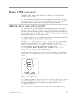
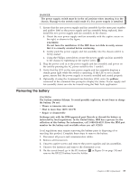
Chapter 4. FRU replacement Attention: Read "Safety notices and labels" on page xiii before removing or installing any components. The field replaceable units (FRUs) in the SAN48B-5 can be removed and replaced without special tools. The switch can continue operating during many of the FRU replacements if the conditions specified in the procedure are followed. Replacing a power supply and fan assembly The SAN48B-5 fans are fixed inside the combined power supply and fan FRU to provide necessary airflow to cool the whole system. There are two fans located in each FRU. The system software sets fan speed and measures their speeds through the tachometer interface. The airflow in the SAN48B-5 is from the port side (intake) through the switch to the non-port side (exhaust). The two power supply and fan assembly FRU units are hot-swappable if replaced one at a time. They are identical and fit into either slot. Attention: A new FRU must have the same part number (P/N) as the FRU being replaced. The manufacturing P/N is located on the top of the FRU. If a mismatched power source or fan assembly is installed by mistake, a warning is sent to the console. The warning messages will be similar to the following:[WARNING, BR6510, MISMATCH in PSU-FAN FRUS Air Flow direction. Replace PSU with fan air flows in same direction. Each power supply/fan assembly has an exhaust airflow label on the faceplate to indicate that the assembly exhausts air (see Figure 13) out the non-port side of the switch. E nety008 AIRFLOW Figure 13. Exhaust airflow label The E symbol indicates an exhaust FRU. This unit pulls air in from the port side of the switch and exhausts it out the non-port side. This is generally referred to as non-port side exhaust airflow. This is reported as Reverse airflow by the chassisShow command. See the samples below for the Fan Direction values in the chassisShow output © Copyright IBM Corp. 2011 29
-
 1
1 -
2
-
3
-
4
-
5
-
6
-
7
-
8
-
9
-
10
-
11
-
12
-
13
-
14
-
15
-
16
-
17
-
18
-
19
-
20
-
21
-
22
-
23
-
24
-
25
-
26
-
27
-
28
-
29
-
30
-
31
-
32
-
33
-
34
-
35
-
36
-
37
-
38
-
39
-
40
-
41
-
42
-
43
-
44
-
45
-
46
-
47
-
48
-
49
-
 50
50 -
 51
51 -
 52
52 -
 53
53 -
 54
54 -
 55
55 -
 56
56 -
 57
57 -
 58
58 -
 59
59 -
 60
60 -
61
-
62
-
63
-
64
-
65
-
66
-
67
-
68
-
69
-
70
-
71
-
72
-
73
-
74
-
75
-
76
-
77
-
78
 |
 |