IBM 2498-B40 User Guide - Page 38
Attaching the rear brackets to the front brackets
 |
View all IBM 2498-B40 manuals
Add to My Manuals
Save this manual to your list of manuals |
Page 38 highlights
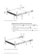
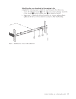
2 1 b48f003 3 4 Figure 5. Position the switch in the cabinet Attaching the rear brackets to the front brackets Complete the following steps to attach the rear brackets to the front brackets. 1. Position the right rear bracket 2 inside the right front bracket 1 , as shown in Figure 6. 2. Attach the brackets using four 6-32 x 1/4 in. screws 4 . 3. Adjust the brackets to cabinet depth and tighten the screws to a torque of 9 in-lb (10 cm-kg). 4. Repeat step 1 through step 3 to attach the left rear bracket 3 to the left front bracket. 3 4 b48f004 Figure 6. Position the rear and front brackets 12 SAN48B-5 Installation, Service, and User Guide 2 1
-
 1
1 -
2
-
3
-
4
-
5
-
6
-
7
-
8
-
9
-
10
-
11
-
12
-
13
-
14
-
15
-
16
-
17
-
18
-
19
-
20
-
21
-
22
-
23
-
24
-
25
-
26
-
27
-
28
-
29
-
30
-
31
-
32
-
 33
33 -
 34
34 -
 35
35 -
 36
36 -
 37
37 -
 38
38 -
 39
39 -
 40
40 -
 41
41 -
 42
42 -
 43
43 -
44
-
45
-
46
-
47
-
48
-
49
-
50
-
51
-
52
-
53
-
54
-
55
-
56
-
57
-
58
-
59
-
60
-
61
-
62
-
63
-
64
-
65
-
66
-
67
-
68
-
69
-
70
-
71
-
72
-
73
-
74
-
75
-
76
-
77
-
78
 |
 |

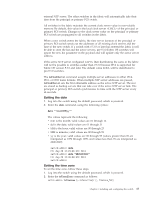
Attaching the rear brackets to the front brackets
Complete the following steps to attach the rear brackets to the front brackets.
1.
Position the right rear bracket
±2²
inside the right front bracket
±1²
, as shown
in Figure 6.
2.
Attach the brackets using four 6-32 x 1/4 in. screws
±4²
.
3.
Adjust the brackets to cabinet depth and tighten the screws to a torque of 9
in-lb (10 cm-kg).
4.
Repeat step 1 through step 3 to attach the left rear bracket
±3²
to the left front
bracket.
4
2
3
1
b48f003
Figure 5. Position the switch in the cabinet
2
1
3
4
b48f004
Figure 6. Position the rear and front brackets
12
SAN48B-5 Installation, Service, and User Guide