IBM 2498-B40 User Guide - Page 59
Removing the battery, Heat to more than 100°C 212°F
 |
View all IBM 2498-B40 manuals
Add to My Manuals
Save this manual to your list of manuals |
Page 59 highlights
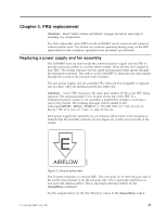
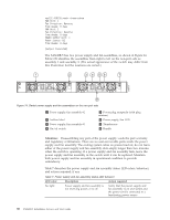
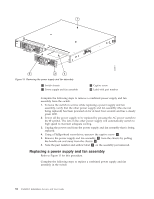
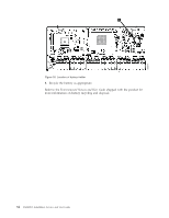
DANGER The power supply switch must be in the off position when inserting it in the chassis. Damage to the switch could result if a live power supply is installed. 1. Ensure that the new power supply and fan assembly has the same part number and airflow label as the power supply and fan assembly being replaced, then install the new power supply and fan assembly in the chassis: a. Orient the new power supply and fan assembly with the captive screw on the right, as shown in the figure. CAUTION: Do not force the installation. If the FRU does not slide in easily, ensure that it is correctly oriented before continuing. b. Gently push the power supply and fan assembly into the chassis until it is firmly seated. c. Using the Phillips screwdriver, secure the power supply and fan assembly to the chassis by tightening in the captive screw 3 . 2. Plug the power cord in to the power supply and fan assembly and power on the unit by pressing the AC power switch to the | symbol. 3. Verify that the LED on the new power supply and fan assembly displays a steady green light while the switch is operating. If the LED is not a steady green, ensure that the power supply is securely installed and seated properly. 4. Optionally, if using the Command Line Interface (CLI), enter the psShow command at the command line prompt to display the status. Power supply and fan assembly status can also be viewed using the Web Tools application. Removing the battery CAUTION: The battery contains lithium. To avoid possible explosion, do not burn or charge the battery. Do not: v Throw or immerse into water v Heat to more than 100°C (212°F) v Repair or disassemble Exchange only with the IBM-approved part. Recycle or discard the battery as instructed by local regulations. In the United States, IBM has a process for the collection of this battery. For information, call 1-800-426-4333. Have the IBM part number for the battery unit available when you call. (C003) Local regulations may require removing the battery prior to disposing of or recycling this product. Complete these steps to remove the battery. 1. Disconnect all power and communication cables. 2. Remove all transceivers. 3. Unscrew captive screws and remove the power supplies and fan assemblies. 4. Unscrew the fasteners and remove the sheetmetal cover. 5. On the circuit board, go to the B1 location ( 1 in Figure 16 on page 34) and remove the BR1225 battery from the holder. Chapter 4. FRU replacement 33
-
 1
1 -
2
-
3
-
4
-
5
-
6
-
7
-
8
-
9
-
10
-
11
-
12
-
13
-
14
-
15
-
16
-
17
-
18
-
19
-
20
-
21
-
22
-
23
-
24
-
25
-
26
-
27
-
28
-
29
-
30
-
31
-
32
-
33
-
34
-
35
-
36
-
37
-
38
-
39
-
40
-
41
-
42
-
43
-
44
-
45
-
46
-
47
-
48
-
49
-
50
-
51
-
52
-
53
-
 54
54 -
 55
55 -
 56
56 -
 57
57 -
 58
58 -
 59
59 -
 60
60 -
 61
61 -
 62
62 -
 63
63 -
 64
64 -
65
-
66
-
67
-
68
-
69
-
70
-
71
-
72
-
73
-
74
-
75
-
76
-
77
-
78
 |
 |
