IBM 2498-B40 User Guide - Page 35
Installing in an EIA cabinet, Time required, Parts list, Description, Quantity
 |
View all IBM 2498-B40 manuals
Add to My Manuals
Save this manual to your list of manuals |
Page 35 highlights
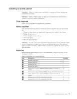
Installing in an EIA cabinet Attention: Refer to "Safety notices and labels" on page xiii before starting any installation procedure. Attention: Refer to "Rack safety" on page xix for danger and caution notices related to rack and cabinet installations. Time required Allow 15 to 30 minutes to complete this procedure. Items required You need the following items to install the switch using the slim rail rack mount kit: v Clamps or other means of temporarily supporting the switch in the cabinet v Phillips #2 screwdriver v 1/4 in. straight slot screwdriver v 1U of rack space v Slim rail rack mount kit Attention: Use the exact screws specified in the procedure for use with the switch chassis. Using screws longer than 3/16 in. can damage the switch. The different types of screws are listed in Table 3. Make sure that you tighten all screws used in this procedure. Parts list Ensure that the items listed in Table 3 and illustrated in Figure 3 on page 10 are included in the kit. Table 3. Parts list for slim rail rack mount kit Item 1 2 3 4 5 6 7 8 9 Description Quantity Bracket, front right 1 Bracket, front left 1 Bracket, rear left 1 Bracket, rear right 1 Screw, 8-32 x 5/16 in., panhead Phillips (torque to 15 in-lb, 17 10 cm-kg) Screw, 6-32 x 1/4 in., flathead Phillips (torque to 9 in-lb, 10 cm-kg) 8 Screw, 10-32 x 5/8 in., panhead Phillips (torque to 25 in-lb, 29 8 cm-kg) Retainer nut, 10-32, (for round-hole rack rails) 8 Retainer nut, 10-32, (for square-hole rack rails) 8 Chapter 2. Installing and configuring the switch 9
-
 1
1 -
2
-
3
-
4
-
5
-
6
-
7
-
8
-
9
-
10
-
11
-
12
-
13
-
14
-
15
-
16
-
17
-
18
-
19
-
20
-
21
-
22
-
23
-
24
-
25
-
26
-
27
-
28
-
29
-
 30
30 -
 31
31 -
 32
32 -
 33
33 -
 34
34 -
 35
35 -
 36
36 -
 37
37 -
 38
38 -
 39
39 -
 40
40 -
41
-
42
-
43
-
44
-
45
-
46
-
47
-
48
-
49
-
50
-
51
-
52
-
53
-
54
-
55
-
56
-
57
-
58
-
59
-
60
-
61
-
62
-
63
-
64
-
65
-
66
-
67
-
68
-
69
-
70
-
71
-
72
-
73
-
74
-
75
-
76
-
77
-
78
 |
 |
