IBM 2498-B40 User Guide - Page 37
Installing the switch in the cabinet, 8 in. screws
 |
View all IBM 2498-B40 manuals
Add to My Manuals
Save this manual to your list of manuals |
Page 37 highlights
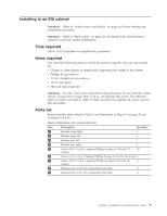
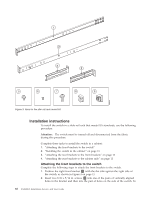
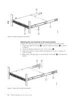
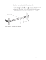
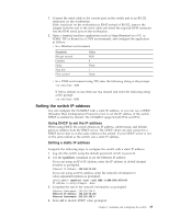
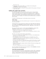
install the switch in a recessed position in the cabinet, use the bracket holes that are set back from the end of the bracket. 3. Insert each 8-32 x 5/16 in. screw through the holes in the bracket and into the corresponding hole in the switch and tighten all 8-32 x 5/16 in. screws to a torque of 15 in-lb (17 cm-kg). 4. Repeat step 1 through step 3 to attach the left front bracket 2 to the left side of the switch. 2 b48f002 1 3 Figure 4. Position the front bracket Installing the switch in the cabinet Complete the following steps to install the switch in the cabinet. 1. Position the switch in the cabinet, as shown in Figure 5 on page 12, providing temporary support under the switch until the rail kit is secured to the cabinet. 2. Attach the right front bracket 1 to the right front rack rail using two 10-32 x 5/8 in. screws 3 and two retainer nuts 4 . 3. Repeat step 2 to attach the left front bracket 2 to the left front rack rail and tighten all 10-32 x 5/8 in. screws to a torque of 25 in-lb (29 cm-kg). Chapter 2. Installing and configuring the switch 11
-
 1
1 -
2
-
3
-
4
-
5
-
6
-
7
-
8
-
9
-
10
-
11
-
12
-
13
-
14
-
15
-
16
-
17
-
18
-
19
-
20
-
21
-
22
-
23
-
24
-
25
-
26
-
27
-
28
-
29
-
30
-
31
-
 32
32 -
 33
33 -
 34
34 -
 35
35 -
 36
36 -
 37
37 -
 38
38 -
 39
39 -
 40
40 -
 41
41 -
 42
42 -
43
-
44
-
45
-
46
-
47
-
48
-
49
-
50
-
51
-
52
-
53
-
54
-
55
-
56
-
57
-
58
-
59
-
60
-
61
-
62
-
63
-
64
-
65
-
66
-
67
-
68
-
69
-
70
-
71
-
72
-
73
-
74
-
75
-
76
-
77
-
78
 |
 |
