IBM 2498-B40 User Guide - Page 33
Planning for cable management, Items required for installation - sfp
 |
View all IBM 2498-B40 manuals
Add to My Manuals
Save this manual to your list of manuals |
Page 33 highlights
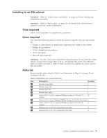
v The cabinet is secured to ensure stability in case of unexpected movement, such as an earthquake. Planning for cable management Attention: The minimum bend radius for a 50 micron cable is 2 inches under full tensile load and 1.2 inches with no tensile load. Cables can be organized and managed in a variety of ways, for example, using cable channels on the sides of the cabinet or patch panels to minimize cable management. Following is a list of recommendations: v Plan for rack space required for cable management before installing the switch. v Leave at least 1 m (3.28 ft) of slack for each port cable. This provides room to remove and replace the switch, allows for inadvertent movement of the rack, and helps prevent the cables from being bent to less than the minimum bend radius. v If you are using ISL Trunking, consider grouping cables by trunking groups. The cables used in trunking groups must meet specific requirements, as described in the Fabric OS Administrator's Guide. v For easier maintenance, label the fiber optic cables and record the devices to which they are connected. v Keep LEDs visible by routing port cables and other cables away from the LEDs. v Use hook and loop style straps to secure and organize fiber optic cables. Do not use tie wraps with optical cables; they can be easily overtightened and can damage the optic fibers. Items required for installation The following items are required for installing, configuring and connecting the SAN48B-5 for use in a network and fabric: v Workstation with an installed terminal emulator, such as HyperTerminal. v Unused IP address and corresponding subnet mask and gateway address v Serial cable (provided) if not using EZSwitch Setup v Ethernet cable v Brocade-branded SFP+s and compatible cables (Brocade-branded 16 Gbps SFP+s are required for 16 Gbps performance), as required v Access to an FTP server or the USB device for backing up the switch configuration (optional) Setting up the switch as a standalone unit Attention: Refer to "Safety notices and labels" on page xiii before starting any installation procedure. To install the switch as a standalone unit, use the following procedure: 1. Unpack the switch and verify that all items listed in "Items included with the switch" on page 5 are present and undamaged. 2. Clean the four corner depressions on the bottom of the switch enclosure, place an adhesive rubber foot in each one, and firmly press into place. The rubber feet on the switch help prevent the switch from sliding off the supporting surface. 3. Place the switch on a flat, sturdy surface. Chapter 2. Installing and configuring the switch 7
-
 1
1 -
2
-
3
-
4
-
5
-
6
-
7
-
8
-
9
-
10
-
11
-
12
-
13
-
14
-
15
-
16
-
17
-
18
-
19
-
20
-
21
-
22
-
23
-
24
-
25
-
26
-
27
-
 28
28 -
 29
29 -
 30
30 -
 31
31 -
 32
32 -
 33
33 -
 34
34 -
 35
35 -
 36
36 -
 37
37 -
 38
38 -
39
-
40
-
41
-
42
-
43
-
44
-
45
-
46
-
47
-
48
-
49
-
50
-
51
-
52
-
53
-
54
-
55
-
56
-
57
-
58
-
59
-
60
-
61
-
62
-
63
-
64
-
65
-
66
-
67
-
68
-
69
-
70
-
71
-
72
-
73
-
74
-
75
-
76
-
77
-
78
 |
 |
