IBM 2498-B40 User Guide - Page 56
LED color, Description, Action required - warranty
 |
View all IBM 2498-B40 manuals
Add to My Manuals
Save this manual to your list of manuals |
Page 56 highlights
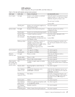
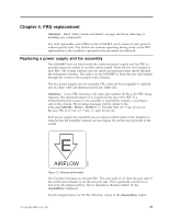
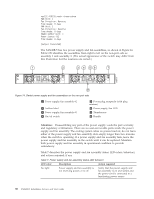
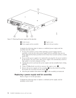
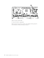
ras222:FID128:root> chassisshow FAN Unit: 1 Fan Direction: Reverse Time Awake: 0 days FAN Unit: 2 Fan Direction: Reverse Time Awake: 0 days POWER SUPPLY Unit: 1 Power Source: DC Time Awake: 0 days (output truncated) The SAN48B-5 has two power supply and fan assemblies, as shown in Figure 14. Fabric OS identifies the assemblies from right to left on the non-port side as assembly 1 and assembly 2. (The actual appearance of the switch may differ from this illustration but the locations are correct.) 1 2 3 4 56 7 E AIRFL OW E AIRFL OW b48f010 8 Figure 14. Switch power supply and fan assemblies on the non-port side 1 Power supply/fan assembly #2 2 Airflow label 3 Power supply/fan assembly #1 4 On/off switch 5 Power plug receptacle (with plug retainer) 6 Power supply/fan LED 7 Thumbscrew 8 Handle Attention: Disassembling any part of the power supply voids the part warranty and regulatory certifications. There are no user-serviceable parts inside the power supply and fan assembly. The cooling system relies on pressurized air, do not leave either of the power supply and fan assembly slots empty longer than two minutes when the switch is operating. If a power supply and fan assembly fails, leave the power supply and fan assembly in the switch until it can be replaced. Maintain both power supply and fan assembly in operational condition to provide redundancy. Table 7 describes the power supply and fan assembly status LED colors, behaviors, and actions required, if any. Table 7. Power supply and fan assembly status LED behavior LED color Description Action required No light Power supply and fan assembly is not receiving power, or is off. Verify that the power supply and fan assembly is on and seated and the power cord is connected to a functioning power source. 30 SAN48B-5 Installation, Service, and User Guide
-
 1
1 -
2
-
3
-
4
-
5
-
6
-
7
-
8
-
9
-
10
-
11
-
12
-
13
-
14
-
15
-
16
-
17
-
18
-
19
-
20
-
21
-
22
-
23
-
24
-
25
-
26
-
27
-
28
-
29
-
30
-
31
-
32
-
33
-
34
-
35
-
36
-
37
-
38
-
39
-
40
-
41
-
42
-
43
-
44
-
45
-
46
-
47
-
48
-
49
-
50
-
 51
51 -
 52
52 -
 53
53 -
 54
54 -
 55
55 -
 56
56 -
 57
57 -
 58
58 -
 59
59 -
 60
60 -
 61
61 -
62
-
63
-
64
-
65
-
66
-
67
-
68
-
69
-
70
-
71
-
72
-
73
-
74
-
75
-
76
-
77
-
78
 |
 |
