IBM 2498-B40 User Guide - Page 58
Replacing a power supply and fan assembly, the handle out and away from the chassis
 |
View all IBM 2498-B40 manuals
Add to My Manuals
Save this manual to your list of manuals |
Page 58 highlights
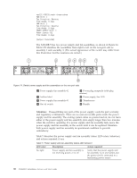
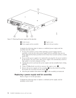
1 b48f011 2 3 4 Figure 15. Removing the power supply and fan assembly 1 Switch chassis 2 Power supply and fan assembly 3 Captive screw 4 Label with part number Complete the following steps to remove a combined power supply and fan assembly from the switch. 1. To leave the switch in service while replacing a power supply and fan assembly, verify that the other power supply and fan assembly (the one not being replaced) has been powered on for at least four seconds and has a steady green LED. 2. Power off the power supply to be replaced by pressing the AC power switch to the O symbol. The fans in the other power supply will automatically switch to high speed to maintain adequate cooling. 3. Unplug the power cord from the power supply and fan assembly that is being replaced. 4. Using a Phillips-head screwdriver, unscrew the captive screw 3 . 5. Remove the power supply and fan assembly 2 from the chassis by pulling the handle out and away from the chassis 1 . 6. Note the part number and airflow label 4 on the assembly just removed. Replacing a power supply and fan assembly Refer to Figure 15 for this procedure. Complete the following steps to replace a combined power supply and fan assembly in the switch 32 SAN48B-5 Installation, Service, and User Guide
-
 1
1 -
2
-
3
-
4
-
5
-
6
-
7
-
8
-
9
-
10
-
11
-
12
-
13
-
14
-
15
-
16
-
17
-
18
-
19
-
20
-
21
-
22
-
23
-
24
-
25
-
26
-
27
-
28
-
29
-
30
-
31
-
32
-
33
-
34
-
35
-
36
-
37
-
38
-
39
-
40
-
41
-
42
-
43
-
44
-
45
-
46
-
47
-
48
-
49
-
50
-
51
-
52
-
 53
53 -
 54
54 -
 55
55 -
 56
56 -
 57
57 -
 58
58 -
 59
59 -
 60
60 -
 61
61 -
 62
62 -
 63
63 -
64
-
65
-
66
-
67
-
68
-
69
-
70
-
71
-
72
-
73
-
74
-
75
-
76
-
77
-
78
 |
 |
