IBM 3580-L23 Setup Guide - Page 25
Step 7. Connecting Power, Step 8. Running the Fast Read/Write Test, For this test
 |
View all IBM 3580-L23 manuals
Add to My Manuals
Save this manual to your list of manuals |
Page 25 highlights
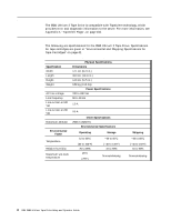
Step 7. Connecting Power __ 1. Ensure that the power switch on the 3580 Ultrium 2 Tape Drive is set to off by pressing 0 on the switch (see 8 in Figure 2 on page 7). __ 2. Plug the power cord into the 3580 Ultrium 2 Tape Drive 7 , then plug the other end into a grounded electrical outlet. __ 3. Because the 3580 Ultrium 2 Tape Drive may not complete the Power-On Self Test (POST) without SCSI termination, ensure that a terminator (or SCSI bus with termination) is connected to one of the two SCSI connectors at the rear of the unit. Note: LVD and HVD/DIFF terminators cannot be intermixed. __ 4. Power-on the 3580 Ultrium 2 Tape Drive by pressing | on the power switch. The tape drive runs the POST, which checks all hardware except the drive head. During the POST, the Single-Character Display flashes several segmented characters. Each segmented character respresents a test performed during the POST. When the POST finishes, the Single-Character Display momentarily lights all 8 segments and then goes blank. At the outset of the POST, the following message appears in the message display for 90 seconds: Power On Self Test In Progress v If the test succeeds, the following message appears in the message display for 5 seconds: Drive FW xxxx Display FW xxxx followed by: Ultrium Tape Drive Drive Empty v If a failure occurs, the following message appears in the message display: ERROR! SELF TEST FAILURE Step 8. Running the Fast Read/Write Test The Fast Read/Write Test performs procedures to ensure that the drive can read from and write to tape. The diagnostic takes approximately 5 minutes to complete and loops continually until you halt it. To halt the diagnostic, press the unload button. The diagnostic will continue to the end of its loop and then stop. Attention: For this test, use only a scratch (blank) data cartridge or a cartridge that may be overwritten. During the test, the drive overwrites the data on the cartridge. __ 1. Make sure that no cartridge is in the drive. __ 2. Make sure that the following message appears on the message display (you may need to turn the power off, then on again for the message to appear). Chapter 2. Installing 9
-
 1
1 -
2
-
3
-
4
-
5
-
6
-
7
-
8
-
9
-
10
-
11
-
12
-
13
-
14
-
15
-
16
-
17
-
18
-
19
-
 20
20 -
 21
21 -
 22
22 -
 23
23 -
 24
24 -
 25
25 -
 26
26 -
 27
27 -
 28
28 -
 29
29 -
 30
30 -
31
-
32
-
33
-
34
-
35
-
36
-
37
-
38
-
39
-
40
-
41
-
42
-
43
-
44
-
45
-
46
-
47
-
48
-
49
-
50
-
51
-
52
-
53
-
54
-
55
-
56
-
57
-
58
-
59
-
60
-
61
-
62
-
63
-
64
-
65
-
66
-
67
-
68
-
69
-
70
-
71
-
72
-
73
-
74
-
75
-
76
-
77
-
78
-
79
-
80
-
81
-
82
-
83
-
84
-
85
-
86
-
87
-
88
-
89
-
90
-
91
-
92
-
93
-
94
-
95
-
96
-
97
-
98
-
99
-
100
-
101
-
102
-
103
-
104
-
105
-
106
-
107
-
108
-
109
-
110
-
111
-
112
-
113
-
114
-
115
-
116
-
117
-
118
-
119
-
120
-
121
-
122
-
123
-
124
-
125
-
126
-
127
-
128
-
129
-
130
-
131
-
132
-
133
-
134
-
135
-
136
-
137
-
138
-
139
-
140
-
141
-
142
-
143
-
144
-
145
-
146
-
147
-
148
-
149
 |
 |
