IBM 867431X Hardware Maintenance Manual - Page 104
Using the computer as a remote console, Serial port, Viewing or changing the serial-port assignments
 |
View all IBM 867431X manuals
Add to My Manuals
Save this manual to your list of manuals |
Page 104 highlights
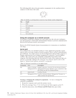
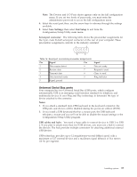
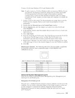
The following table shows the pin-number assignments for the auxiliary-device connector on the end of the cable. 6 4 2 5 3 1 Table 13. Auxiliary or pointing-device-connector (6 pin female) number assignments Pin Signal 1 Data 2 Not connected 3 Ground 4 +5 V dc 5 Clock 6 Not connected Using the computer as a remote console If you plan to install the computer in a rack away from the end-user workspace, you must purchase a third-party KVM Extender System to provide communication between the keyboard, mouse, and monitor. Refer to the KVM Extender System documentation for instructions on installation and setup. Serial port Your computer has one standard serial port. Some application programs require specific ports, and some modems function properly only at certain communication port addresses. You might need to use the Configuration/Setup Utility program to change communication port address assignments to prevent or resolve address conflicts. This serial port is also manually configurable from inside of the computer. The following table lists the function of each of the connectors that you can use to manually configure the serial port. You will also need to refer to the figure in "System board options connectors" on page 44. Table 14. Serial port connectors on the system board Connectors Port Description J52 Serial A/Systems Default connection. Used by OS and Advanced System Management Port Management Processor. Modem can be connected so that the system can dial out during problems. J51 Serial Port B Used by OS only. J53 Management Port Used by Advanced System Management Processor to utilize modem dial up functions. Viewing or changing the serial-port assignments: To view or change the serial-port assignments: 1. Restart the computer and watch the monitor screen. 2. When the message Press F1 for Configuration/Setup appears, press F1. 3. From the main menu, select Devices and I/O Ports; then, press Enter. 96 Hardware Maintenance Manual: xSeries 330 Type 8674, IntelliStation R Pro Type 6851, and Network Equipment Building System Type 8674
-
 1
1 -
2
-
3
-
4
-
5
-
6
-
7
-
8
-
9
-
10
-
11
-
12
-
13
-
14
-
15
-
16
-
17
-
18
-
19
-
20
-
21
-
22
-
23
-
24
-
25
-
26
-
27
-
28
-
29
-
30
-
31
-
32
-
33
-
34
-
35
-
36
-
37
-
38
-
39
-
40
-
41
-
42
-
43
-
44
-
45
-
46
-
47
-
48
-
49
-
50
-
51
-
52
-
53
-
54
-
55
-
56
-
57
-
58
-
59
-
60
-
61
-
62
-
63
-
64
-
65
-
66
-
67
-
68
-
69
-
70
-
71
-
72
-
73
-
74
-
75
-
76
-
77
-
78
-
79
-
80
-
81
-
82
-
83
-
84
-
85
-
86
-
87
-
88
-
89
-
90
-
91
-
92
-
93
-
94
-
95
-
96
-
97
-
98
-
 99
99 -
 100
100 -
 101
101 -
 102
102 -
 103
103 -
 104
104 -
 105
105 -
 106
106 -
 107
107 -
 108
108 -
 109
109 -
110
-
111
-
112
-
113
-
114
-
115
-
116
-
117
-
118
-
119
-
120
-
121
-
122
-
123
-
124
-
125
-
126
-
127
-
128
-
129
-
130
-
131
-
132
-
133
-
134
-
135
-
136
-
137
-
138
-
139
-
140
-
141
-
142
-
143
-
144
-
145
-
146
-
147
-
148
-
149
-
150
-
151
-
152
-
153
-
154
-
155
-
156
-
157
-
158
-
159
-
160
-
161
-
162
-
163
-
164
-
165
-
166
-
167
-
168
-
169
-
170
-
171
-
172
-
173
-
174
-
175
-
176
-
177
-
178
-
179
-
180
-
181
-
182
-
183
-
184
-
185
-
186
-
187
-
188
-
189
-
190
-
191
-
192
 |
 |
