IBM 867431X Hardware Maintenance Manual - Page 117
Cabling the RS-485 connectors, RS-485 A and RS-485 B.
 |
View all IBM 867431X manuals
Add to My Manuals
Save this manual to your list of manuals |
Page 117 highlights
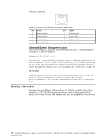
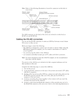
Note: Refer to the following illustration to locate the connectors on the back of your server. Ethernet 1 speed indicator (green) Ethernet 1 link indicator (green) Advanced System Management RS-485 connectors C2T (Out) connector Select light (green) Ethernet 2 link indicator (green) Ethernet 2 speed indicator (green) USB 2 connector Power-on light (green) USB 1 connector System error light (amber) Serial connector C2T (In) connector The ASM connectors on the back of the server are referred to in this book as RS-485 (A) and RS-485 (B). Cabling the RS-485 connectors You can use the RS-485 connectors to create an ASM bus between several xSeries 330 servers or other servers. Before you begin, review the following: v The ASM bus is designed to connect up to 12 units or servers. When using the IBM Remote Supervisor adapter, you can connect a maximum of 11 units or servers together. v You can hot-swap the cables in the ASM bus. v Use standard unshielded twisted pair (UTP) cables with RJ-45 connectors. Note: For more information about the ASM PCI adapter, see the documentation that came with the adapter. The servers in the ASM bus are referred to by their assigned addresses and not their positions in the rack. Complete the following steps to connect the ASM bus: 1. Turn off the servers. 2. Locate the RS-485 connectors on the rear of the servers and several UTP cables with RJ-45 connectors. 3. Starting at the top server in the ASM bus, connect one end of the cable into the RS-485 (B) connector and the other end of the cable into the RS-485 (A) connector of the next server. 4. Continue connecting the servers together in this manner until you reach the second-to-last server in the ASM bus. 5. Connect a cable from the RS-485 (B) connector of the second-to-last server to the RS-485 (B) connector of the last server. Refer to the following illustration to Installing options 109
-
 1
1 -
2
-
3
-
4
-
5
-
6
-
7
-
8
-
9
-
10
-
11
-
12
-
13
-
14
-
15
-
16
-
17
-
18
-
19
-
20
-
21
-
22
-
23
-
24
-
25
-
26
-
27
-
28
-
29
-
30
-
31
-
32
-
33
-
34
-
35
-
36
-
37
-
38
-
39
-
40
-
41
-
42
-
43
-
44
-
45
-
46
-
47
-
48
-
49
-
50
-
51
-
52
-
53
-
54
-
55
-
56
-
57
-
58
-
59
-
60
-
61
-
62
-
63
-
64
-
65
-
66
-
67
-
68
-
69
-
70
-
71
-
72
-
73
-
74
-
75
-
76
-
77
-
78
-
79
-
80
-
81
-
82
-
83
-
84
-
85
-
86
-
87
-
88
-
89
-
90
-
91
-
92
-
93
-
94
-
95
-
96
-
97
-
98
-
99
-
100
-
101
-
102
-
103
-
104
-
105
-
106
-
107
-
108
-
109
-
110
-
111
-
 112
112 -
 113
113 -
 114
114 -
 115
115 -
 116
116 -
 117
117 -
 118
118 -
 119
119 -
 120
120 -
 121
121 -
 122
122 -
123
-
124
-
125
-
126
-
127
-
128
-
129
-
130
-
131
-
132
-
133
-
134
-
135
-
136
-
137
-
138
-
139
-
140
-
141
-
142
-
143
-
144
-
145
-
146
-
147
-
148
-
149
-
150
-
151
-
152
-
153
-
154
-
155
-
156
-
157
-
158
-
159
-
160
-
161
-
162
-
163
-
164
-
165
-
166
-
167
-
168
-
169
-
170
-
171
-
172
-
173
-
174
-
175
-
176
-
177
-
178
-
179
-
180
-
181
-
182
-
183
-
184
-
185
-
186
-
187
-
188
-
189
-
190
-
191
-
192
 |
 |
